(c) 1999,2025 Peter McCollum
Mystery Radios
The equipment presented in this section has the "look and feel" of clandestine radio gear, but only very limited information is available at this time.
Set #1
[Additional info on this set can be found in "Wireless for the Warrior, Vol 4", by Meulstee and Staritz.]
This set was found in London, and has no markings other than a U.S. inspection stamp. The transmitter uses three 3S4 tubes (one osc., two power amps in parallel). The receiver tubes are five of the 1T4, 1U5, etc., series of battery tubes.
It was described in an Electronic Industries magazine article in October 1944, as a briefcase transceiver. The set was developed by Crosley Corp. under a "development order" by the U.S. Signal Corps. The specifications were almost entirely related to physical size and frequency coverage.
The set appears to include an alternate packaging of the SCR-295, pictured in “Signal Corps Radio Sets, Front Views, Receivers and Transmitters”, dated January 1943. Shown are versions by Crosley and General Electric, with dates of December 1941. The SCR-295 appears to be a body-worn receiver only (no transmitter).
A front view, with the receiver stacked on top of the transmitter. Photo courtesy of Robin Greenwood.
The Crosley version of the SCR-295. This is presumed to be a receiver and battery box only (no transmitter).
A view showing the insides of the low, flat cases. Photo courtesy of Robin Greenwood.
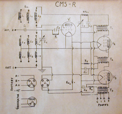
Set #2 - CMS
This Navy set has certain features that are consistent with a 'clandestine radio', such as the wood suitcase-style case. However, the technology is outdated (given late WWII), and some features are inappropriate to clandestine use, such as the simple regenerative receiver design, and the AM-voice transmitter capability. Use by 'Coast Watchers' is one possibility that has been suggested. Another suggestion is that it is the result of a contract that pre-dates the war, and for some reason its introduction was delayed.
The CMS tunes 3.1 to 13.5 MC. The xmtr can operate with either 6V6 or 6L6 tubes.
More specific historical info is needed.
Info from Keith Melton, via an e-mail from Gary Sharp:
"I researched this set about 30 years ago. It is not a clandestine radio, but rather a special purpose set intended to provide for communication from a member of the crew on shore back to the ship. The radio, circa WW2, is sometimes referenced during an amphibious invasion where it was sometimes necessary to coordinate the waves of material and personnel landing on the beach head with the vessels off shore. The USN did not operate agents unilaterally to require clandestine radios."
Comments/rebuttal from Hue Miller:
“The Navy ran clandestine operations in the Philippines, as far as supplying the guerrilla operations, and was involved in China before the Army with the SACO organization. I take the CMS to be an expedient radio intended for the Philippines – perhaps its use was supplanted by the Australian products ATR-4 and 3BZ. The Navy already had plenty of capable shore party radios in the TBX series. Why use a comparatively crude and hard-to-operate CW set for this purpose?” Hue points out that the tube sockets are wired so it can use a variety of 6 and 1.5 volt tubes, both pentodes and triodes, but operates them all in triode mode. This implies that flexibility and simplicity (minimum parts count) were a design goal, although the User Instructions does not mention the possibility of using battery-filament tubes in the transmitter.
Here is the CMS Operating Instructions, courtesy of Dennis Monticelli.
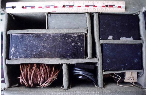
Set #3
The designation of this set is unknown, and no other examples have been seen to date. Perhaps it is a manufacturing prototype, from a company bidding on a contract?
Additional info from the late Bill Howard:
This set came in a canvas bag, similar to a mechanics tool bag. Covers fold over each other and had two snaps to hold it closed. It had a carry sling for over the shoulder carry. In side were 9 compartments. Two small compartments held the receivers, and smaller pockets held the accessories. There was a small compartment which looked to be made for a manual or message pad. A large center compartment held the transmitter. Two smaller compartments held accessories. One had a wooden box, assume there was a box for the other compartment. Set had a transmitter and two receivers but no transmitter power supply. Assume it was lost along the way. Think there was space in the bag for a power supply. Two more compartments were there and it appeared that one could have held the power supply and the other held the key. The larger compartment had an antenna of copper wire that we did not think was original.
The cases reminded me of the SSTR-5 set and they were metal, of the same shape and design. there the similarity ended. The transmitter has a dove tail U shaped bracket on one end into which one of the receivers fits. The cases were painted black. No effort was made to treat the metal so the paint was flaking off.
The receivers are about 4 inches by 4 inches by 3 inches. The receiver is mounted on a metal panel which is held in place by 6 screws. Once the panel is removed the battery compartment is accessible The batteries are BA-231/U for filaments, and 2 45 volt B batteries made by NIHON SEKISO with brand name "Flattery". Batteries are hard to change, require a screwdriver, removal of the set from the case. I do not think these sets were made for extended use. Probably one time use only (short term mission??). Receivers are 5 tube sets, tubes are the submini as used in PRC-6 and PRC-10 radios. In sockets, and covered with a tar like substance. They can not be removed in the field. Front panel controls are the headphone socket (1/8" plug), the On/Off switch, a Ground connection, an antenna connection, a crystal socket and a BFO tuning control. Set is tuned by a crystal to a pre-set frequency. Underside the BFO is a small capacitor, the crystal socket a "module" made of a phenolic material, shaped like an H with the tube sockets mounted three on one side, two on the other. A tar like substance was dripped on the tubes to hold them in place. Resistors and capacitors were mounted on the ends of the "H". The capacitors were the more modern type, like the orange drop capacitors. No schematics were available so I can not comment on the circuit. There were no IF transformers.
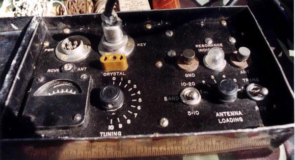
The transmitter was about twice as long as the receiver. The transmitter was mounted on the front panel, again held in place by six screws. Across the top were the power socket, 4 pin connections; a similar socket for the key to be plugged in. Think these are called amphenol connectors. The next row down had the connection for the receiver antenna, the crystal socket, the Ground connection, a tuning lamp, and the Antenna connection. Bottom row had a meter, a rotary control, connected to a small variable capacitor and marked 1 to 10; a band switch marked 5-10 and 10-20, an antenna loading control and a transmit/receive switch. Transmitter components on the under side revealed one 6AG7 tube, held in place by a clamp. The transmitter had a tank coil and antenna loading coil wound on a fibreboard(?) form. Had a small capacitor about 0-300 pf (1 inch long) older US style resistors and modern capacitors. The antenna and ground connectors appear to have been made for the WWII EE-8 field telephone. They were smaller than the standard line terminals. The antenna loading coil had multiple taps connected to the rotary switch which was very small. Definite post war production. There was a small trimmer capacitor wired to the tube socket. This was not user adjustable. There was one four-winding RF choke. Visible in the photograph are two capacitors and 7 resistors ranging from 1/4 watt to a 1 watt resistor, of WWII vintage. The accessories were the post war earphones, 2 sets, indicating that both receivers were expected to be in use at the same time, several crystal socket extenders; 2 jump cables for connecting receiver antenna to transmitter; some wire which I suspect was the "as issued" antenna and a hank of string, probably for getting the antenna hung in a tree. A spare 6AG7 tube was included. Battery for receiver filament was dated 1953. My impression was that this was a prototype set and made in limited quantities.