
(c) 2000,2024 Peter McCollum
Surveillance and Bugging Devices
While the Office of Communications in the Agency handled the traditional communications role, including the design, construction, and use of radio equipment; there was a separate group known as the Technical Services Staff (TSS; formed in 1951, renamed to Technical Services Division in 1960), which was responsible for providing a wide range of devices to operatives; including equipment for audio surveillance, clandestine photography, and lock bypass. In 1973, TSD was renamed the Office of Technical Service (OTS).
[Note: Info on one or more non-U.S. surveillance sets (such as the Czech Tesla-made PR-35) can be found in the “Selected Foreign Sets” section.]
The ASR-1, ASR-2, and SRR-4 Surveillance Receivers
This family of receivers are for general-purpose surveillance work, but were specifically intended for listening to “bug” transmitters. They receive FM, AM, and CW signals in the range of 20-100 MC or 50-200 MC. The design includes 12 or 13 subminiature tubes, plus several germanium diodes, and 3 transistors (in the power supply module).
· ASR-1 model: 20-100 MC, with calibration points every 2 MC, 13 tubes. The RF design is very close (identical?) to the military R-744/PRR.
· SRR-4 or ASR-2 model: 50-200 MC, with calibration points every 5 MC, 12 tubes.
These receivers are ideal for monitoring "bug" transmitters, such as the ST-2A (described below on this page), SRT-5 [ref 147], and RT-3R (described below). An SRR-4 was used in a ‘defensive’ operation in Denmark in 1965 to monitor a meeting in a hotel, by scanning for ‘bugs’ that might be placed by the opposition [ref 146]. The SRR-4 set is featured in H. Keith Melton's book "CIA Special Weapons & Equipment" on page 52.
Following is a likely time-line of the development process, based on declassified documents:
· Early 1956: TSS (Technical Services Staff) wants a surveillance rcvr. TSS will ask the Army Signal Corps about the 'service test results' for their 20-100 MC receiver [presumed to be the R-744/PRR].
· June 1956: TSS starts talking to the maker (Radio Receptor Co.), and has some design changes that they want (such as a more flexible power supply).
· August 1956: Radio Receptor is asked to submit a budget for a separate 50-175 MC rcvr (an additional project to cover higher frequencies).
· November 1956: The project is officially expanded to include both a "lo-band" and "hi-band" version. Requirements are specified to Radio Receptor. 12 hi-band units are initially requested.
· December 1956: The lo-band project is “P-191A”; the hi-band is “P-191B”. Hi-band range is now expected to be 50-250 MC.
· February 1957: Lo-band contract received by Radio Receptor. Hi-band contract probably received at the end of that month.
· May 1957: Lo-band rcvr work is about 50% complete. Work has begun on the AC power supply design (PP-1A/ASR). Hi-band rcvr work is just beginning, including a new RF front end design.
· August 1957: The equipment is now being called "ASR-1" (low band) and "ASR-2" (high band). The first ASR-1 delivery is expected in late October.
· September 1957: 12 ASR-1 units are being built by Radio Receptor. It is stated that the ASR-2 will now be 50-200 MC (ASR-1 is 20-100 MC). Future ASR-1 units will be put out for bid to other contractors. The final model of AC power supply is demonstrated. An "ASR-3" is discussed.
· August 1958: ASR-1 is being used to evaluate the RT-3 surveillance xmtr (Note: This RT-3 is NOT the same as the xmtr in the RS-1 agent radio set. The RT-3 is the predecessor to the RT-3R discussed below).
· 1959, or late 1958: The ASR-2 likely becomes available in the field.
· May 1960: An ASR-1 is used while testing the new RT-3R surveillance xmtr.
· At some point, the ASR-2 becomes known as "SRR-4", and is marked as such on the front panel. The first clear evidence of the SRR-4 nomenclature is in February 1961, when it was used for testing another device. A documented surveillance operation in Copenhagen occurred in March 1965, using an SRR-4 and an SRT-5 transmitter.
Changes noted from the military R-744/PRR to the CIA’s ASR-1:
· Power input connector changed to a different type on the ASR-1: Now it is a U-79/U, which mates with a U-77/U audio plug to support 3 alternate inputs on the same connector.
· Power input on the ASR-1 now supports 110VAC, 220VAC, and 12VDC; or internal batteries. The R-744 supports only 24VDC or batteries. The change from 24V to 12V is sensible, because military vehicles were 24V, while civilian vehicles were 12V.
· Removed the Bandspread knob found on the R-744.
· Audio and Detector output connectors are each a BNC on the ASR-1, instead of a ¼” phone jack. (Detector output is not present on the R-744 and R-744A, but is found on the R-744B).
· Removed the DF Antenna input found on the R-744, and also the antenna selector switch.
· Added the front-panel bulkheads to the ASR-1 for mounting the antenna.
· Removed the dial light dimmer pot from the R-744; it is just an on/off switch on the ASR-1.
· Calibration crystal is now a separate crystal on the ASR-1, instead of inside a plug-in module.
· Case color was changed from O.D. green, to black.
Differences noted between the ASR-1 and the SRR-4:
· Model: ASR-1 (not marked) SRR-4 (marked on front panel)
· Frequency range: 20-100 MC 50-200 MC
· IF stages: four five
· Mixer stage: 6611 tube 1N21B diode
· Local Osc.: two 6612 tubes paralleled single 6051 tube
· Cal. oscillator: separate 2MC xtal 5MC crystal inside a plug-in module
No details of the ASR-2 are known at this time (other than the time-line described above), but it is believed to be the original nomenclature for the SRR-4.
More pictures and details of the SRR-4 can be found here: http://www.cryptomuseum.com/df/srr4/index.htm .
Two subsequent receivers were developed by Radio Receptor under contract RD-114:
· SRR-5: Tunes 50-400 MC in two bands. Available about 1960. Perhaps it is the “ASR-3” mentioned in a meeting report in Sept. 1957? For details, refer to: https://www.cryptomuseum.com/df/srr5/index.htm .
· SRR-8: Tunes 30-1000 MC in four bands. Available (in prototype form) about 1961. For details, refer to: https://www.cryptomuseum.com/df/srr8/index.htm .
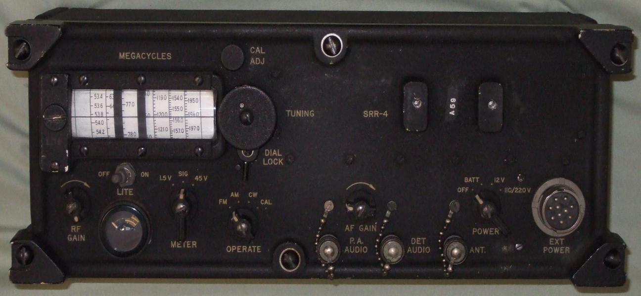
An SRR-4 receiver, serial # A59. Based on tube date codes, it was likely made in 1961 or 1962. The whip antenna can be mounted as shown, or perpendicular to the front panel when the receiver is positioned face-up. The antenna extends to a length of 53 inches. Since the set has a BNC connector for the main audio output, an included accessory is an adaptor to allow a 1/4-inch phone jack to be used with standard headphones. The power cord shown is for 220 VAC operation. This particular unit was part of a "stay-behind" program in Norway. Author's collection.
This composite image shows 3 views of the ASR-1 (top) together with the SRR-4 (bottom). The ASR-1 uses 3 RF amp tubes, a mixer tube, and a pair of tubes for the local oscillator. The SRR-4 uses a 1N21B diode for the mixer, and a single tube for the local oscillator. The Calibration Oscillator module is the only one that is unique to both receivers: the ASR-1 uses a type 473-215, while the SRR-4 uses a type 473-223. All other modules can be found in both receivers.
The 10-pin power input connector mates with a U-77 plug, the same as the audio connector on many 1950's-vintage military radio sets. The CIA may have chosen this type of connector because it is waterproof, durable, and easy to find at that time. The ‘DETector AUDIO’ output is suitable for connection to a tape recorder. The ‘CAL’ setting enables a harmonic oscillator that drives the 1st RF amp stage.
Inside the rear of the case is a "PP-1A/ASR" power supply (the module in the middle), and battery compartments on either side. The batteries (1.5V and 45V) are accessed from panels on each end of the case.
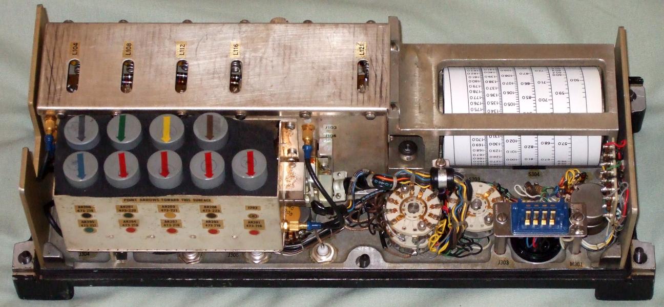
The SRR-4 circuitry includes 9 plug-in modules (the gray objects with colored arrows; the ASR-1 has 8 modules), plus 4 additional subminiature tubes in the RF front-end (6 tubes in the ASR-1). The plug-in modules perform functions such as IF amps, Discriminator, BFO, CAL oscillator, and Audio. The concept of tube-style modules was seen in the military AN/PRC-8/9/10 transceivers since 1951; the IF amp and Discriminator modules are still almost identical circuits, and are pin-compatible with these newer ASR/SRR units. Main chassis components are silver-plated, while rotary switch contacts and mini coax connectors are gold-plated.
An upper view of the SRR-4 chassis, showing the 4 tubes in the RF front-end. Note the 1N21B cartridge-type mixer diode, under the screwdriver cap at bottom-center.
Inside the PP-1A/ASR regulated power supply, providing 45V and 1.5V. Note the two unusual dome-shaped power transistors used in the DC-DC converter. Directly below the transistors is a toroidal inverter transformer, and another early germanium transistor. Several of the original capacitors have been replaced with newer units.
The plug-in modules include an “RR” marking, probably referring to “Radio Receptor”; while the power transformer shows “G.I”, probably for “General Instrument”. G.I. bought Radio Receptor in 1957.
Technical Notes:
· SRR-4: The local oscillator is an unusual type 6051 tube. The datasheet describes it as “suitable for intermittent service applications such as ‘push-to-talk’ transmitters which do not require long life characteristics.”. Also, the ‘design maximum’ filament voltage is 1.38V, not 1.5V. This tube seems like a poor choice for this application, where it may be expected to operate for many hours continuously.
· ASR-1: The meter face is radioactive due to Radium paint on the dial (this is true of the military R-744 also). The SRR-4 is not radioactive.
· The dial lamp is a type 331 (1.35V, 60mA). A type 338 is a fair substitute, at a lower brightness.
The ST-2A Surveillance Transmitter
The ST-2A is one of the earlier models in a long series of equipment. The purpose of a surveillance transmitter (ST) is to transmit the sounds (conversations) from within a room to a person or recording device monitoring a receiver nearby. For example, an ST may be hidden in a hotel room before the targeted person arrives, and the opposition can set up equipment on an adjacent floor to monitor and record any conversations that take place.
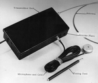
The ST-2A as shown in the manual. The mic is a Shure MC11.
A view of an ST-2A with the cover removed. One of the 1AD4 tubes is visible on the far right. The two gold connectors are for RF out and audio in. On the bottom right corner is an access panel for tuning. The AC power cord comes in from the left.
This model is a hybrid design, using two 1AD4 tubes and 3 type 2N207B transistors. The three transistors are a basic audio amplifier, one tube is the RF oscillator, and the second tube functions as a doubler. The unit operates from 115 or 230 VAC, 50-60 cps, unswitched. The output frequency is in the range of 56 to 84 mc, FM, and produces at least 30 mW of RF power into a 50-ohm load. It measures 5-5/8" X 3" X 1-1/4", and weighs 19 oz. The suggested microphone is a Shure MC11 (1K ohm dynamic, 400-4000 Hz), and the antenna is a 40" length of Amphenol No. 14-500 cable (Amphenol lists this as a "Sub-Minax" cable). The mic input connector is a type SMC, and the RF out is an Amphenol "Sub-Minax" connector.
Referencing the picture above, the major components in the unit, from left to right, are: power transformer, low-voltage rectifiers and filters board, high-voltage rectifiers and filters board, audio board (3 transistors plus a deviation adjustment pot), and RF board.
The only controls or adjustments are an oscillator tuning coil, a doubler tuning coil, and an audio FM deviation control pot. There is an access panel that allows adjustment of the tuning while the cover is in place.
The overall tuning range for the ST-2A is 56 to 84 mc, but each individual unit was pre-tuned at the factory to operate on one of three frequencies: 59 mc, 68 mc, or 77 mc. Each unit has a colored marking on the corner of the case to indicate which of the factory tunings has been applied; the colors are green, blue, and white respectively. According to the manual, each unit can be re-tuned by the user over an 8 mc range, which implies that there are some component differences between the green, blue, and white units.
The power supply provides 2.5 VDC for the tube filaments (1.25 V each, in series); 65 VDC for the tube plates; and 5 VDC for the transistors. Rectifiers are germanium 1N91 and 1N93 types.
The apparent predecessor of the ST-2A, the ST-2, was available before April 1956. The ST-2A was introduced in 1957, undergoing “operational evaluation” in July of that year. There were reliability problems with the 1AD4 tubes - they would often lose filament emission after 50-100 hours of operation. The ST-2A was replaced by the 'Surveillance Radio Transmitter' SRT-3 (see discussion below), which was all solid-state, and about 1/3 the size. At that time the nomenclature changed from ST-x to SRT-x. The SRT-1 and SRT-2 were prototype models that were never generally used. The SRT-3 was a well-used item for a number of years, and was eventually followed by a long series of SRT-x units.
For much more information on this item, refer to https://www.cryptomuseum.com/covert/bugs/st2a/index.htm .
RT-3R Transmitter (also ST-3 and SRT-3)
The ST-3, RT-3R, and SRT-3 are all closely related, and were developed in 1958. The ST-3 is believed to be an all-solid-state implementation of the ST-2A (described above), and still included an AC power supply within the unit. The RT-3R is essentially the same implementation as the ST-3, but without a built-in power supply. The SRT-3 is likely just an alternate name for the RT-3R (a CIA veteran referred to the SRT-3 as the successor to the ST-2A, and a CIA document mentions an “SRT-3R”, confirming the overlap in nomenclature).
The RT-3R includes an attached power cable with a connector on the end. The connector mates with an RT-3PS AC power supply, or with a battery pack as shown in the picture below. This design, with a separate power source, allows for more flexible installations and better security, since the microphone, transmitter, and power source can each be separated by some distance.
The transmitter unit measures 3-13/16” x 1-3/4” x ¾”, and can operate for 360 hours on one battery pack. The transmitted signal is FM; 55-63 MC or 64-72 MC or 73-81 MC (three variants of the transmitter were made). The RT-3R was supplied with a Shure MC30 mic, but was also tested with an RCA BK-6B. Transistors in the circuit are 2N500 and 2N207B, two of each. The manual mentions usage with the ASR-1 and PFR-5 receivers; and a NEMS-Clarke model 1501 used for testing.
RT-3PS supply: 110/220 VAC 50/60 CPS input, 6.5V 15 mA output, with a simple Zener diode regulator.
Note that the “RT-3” nomenclature matches the RS-1 transmitter (which is also “RT-3”). This overlap is because they were produced by separate divisions in the Agency: Office of Communications, vs Technical Services Staff. Other similar devices with names that overlap with Commo equipment: RS-1 Remote Switch; and RT-1, RT-1A, RT-2, and RT-3 Transmitters.
The RT-3R as shown in the manual. The cable marked ‘Parallel Connector’ is showing how another battery pack can be connected to extend the operational life. The microphone is a Shure MC30. The connectors appear to be a type of mini-BNC.
Audio Recorders
In surveillance operations, it is often required to record the intercepted audio. TSS/TSD/OTS used a variety of commercial recorders, and sometimes made modifications for specific purposes. Following is a list of references to commercial recorders from declassified documents, in chronological order:
8/1951 to 4/1953 – The Office of Training (OTR) worked with Revere to develop a “Mobile Audio-Visual Device” to be used for foreign language training in the Field. The setup included a Revere T-500 tape recorder modified to play back 2 channels, and metalized strips on the tape to advance a slide projector.
7/1954 – A Revere T-500 was modified with the “Portable Tape Recorder Amplifier”. Probably involved very early transistors, as the memo mentions other projects using transistors.
12/1956 – TSS discusses replacing Bell recorders with the Ampex model 601. Several modifications are done, including: 1) Allowing 3-3/4 IPS tape speed only; 2) Adding a switch to turn off the motor so that it can be used for quiet audio monitoring; 3) Adding a fuse; 4) Change the head mounting to be plug-in, for easy replacement; 5) Replace the mic connector with a standard ¼” phone jack; 6) Add a battery-operated relay to allow enabling the motor by remote control.
8/1957 – The Revere T-700 is mentioned as equipment on loan to a contractor.
9/1957 – A Revere T-1100 was being used as a Morse code practice aid.
Circa 1960 – The SRR-4 manual describes the audio connection to the Revere T-700 and Ampex 601.
9/1961 – The Revere T-2000 became the replacement for the T-1100, which was no longer manufactured.
4/1962 – These models were on a “Standard Communications Equipment List”: Revere T-2000; Ampex 350 and 601; Precision PS-200 and PS-207; Minicom CM-114, CM-107, and G-100.
1/1963 – Seventy Revere T-2000 recorders purchased.
4/1963 – Six Revere T-202 recorders purchased for use with “secure phone links in the OXCART Operations control room”. OXCART was the A-12 aircraft project, which later evolved into the USAF SR-71. The equipment also included 12 Audiotex inductive telephone pickups.
1964 - The Ampex 614 was a ‘stock item’.
9/1965 – Eight Revere T-3000 recorders received. Three Revere T-11 recorders procured for use in a “special interrogation training center”.
8/1966 – Fifty-two Revere T-3000 recorders received.
12/1966 – Thirteen Revere T-3000 recorders were modified to enable the use of a voice-operated switch.
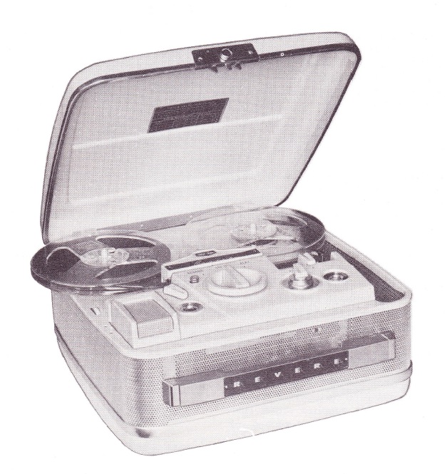
A Revere T-2000 tape recorder, circa 1962.
Small Microphones
For clandestine audio operations (“bugging”), a variety of microphones have been used. The popular choices were typically the smallest and best-performing mics available from private industry. The CIA helped fund some relevant development projects, and developed some modifications to commercial models, but no info has been found describing a microphone actually developed ‘from scratch’ by CIA.
Some specific microphone models known to be used by CIA:
Shure 61B and Brush BL301 – Discussed for use as a ‘contact microphone’ in 1956. A contact mic is a type attached to a wall, and will pick up sounds occurring on the other side of the wall. The Shure 61B is a crystal type, described in the 1957 catalog as: “Vibration Pickup model 61B – Used for locating and measuring vibration […] and a wide variety of scientific and industrial problems.”

Shure 61B, as shown in the 1957 catalog.
RCA BK-6B – A lavalier mic intended for the broadcast industry, beginning in 1957. Response 80-12000 Hz, impedance 250 ohms. More details here: https://www.cryptomuseum.com/covert/mic/typeb/index.htm .

RCA BK-6B, as shown in an advertising brochure.
Shure MC30 – A very small (for the time) dynamic mic, introduced in 1958, mentioned in CIA documents by 1960. Response 400-3500 Hz, impedance 1850 ohms. The series also included the somewhat larger MC11, MC20, and MC14 models. A 1966 Shure catalog says: “The MC Series of microphones have also proven to be extremely useful in concealed microphone applications.” Other versions of the MC30 include the MC30F and MC30J.

Shure MC30. The tiny hole is the sound inlet. Author’s collection.
Shure MC11 – The largest member of the Shure “MC Series”. Response 400-4000 Hz, impedance 1000 ohms. The MC11 is shown in the manual for the ST-2A surveillance transmitter (see earlier on this page).

Shure MC11. Author’s collection.
Brush BA-110 – A crystal microphone, mentioned in CIA documents in 1958 and 1959.

Brush BA-110. The example on the right was used in a CIA safehouse in New York, removed by the author’s father when the safehouse was discontinued. Author’s collection.
American Microphone Company model DD4 - This mic measures 1-5/8" in diameter and is 7/8" thick. It is a dynamic type, and seems to contain a fairly large magnet. A CIA veteran mentioned it to the author, after recognizing a picture I sent. I have since found it in two CIA documents. It is also mentioned in Popular Science magazine, October 1957.
American Microphone Co. DD4 microphone.
In the 1960's, the hearing-aid industry began to use tiny transducers that allowed the “behind-the-ear” type of aid to be developed. These new microphones, mostly from Knowles Electronics, represent a technology that was valuable to OTS/TSD for various types of listening devices. Some Eastern-Bloc countries also procured them for use in their listening devices. Hearing-aid components are ideal for clandestine audio monitoring, because they are optimized for receiving the human voice, while being physically small.
Some specific hearing-aid mic types:
Knowles 1532 dynamic mic, found in the CIA SWM-44B. More info on the SWM-44B is here: https://www.cryptomuseum.com/covert/mic/swm44b/index.htm .

A CIA SWM-44B mic, which contains a Knowles 1532 dynamic hearing-aid element. The silicone casing protects the delicate wiring connected to the mic element, and provides a mechanical ‘shock mount’. Author’s collection.
Knowles BJ-1590 and BJ-1591 (dynamic), and BL-1670 and BL-1671 (ceramic, with FET preamp). In 1970, the CIA commissioned a study to compare these two mic series. The ceramic type has a response peak near 3500 Hz, but overall is fairly flat across the entire voice range, and has a higher output due to the active preamp. The dynamic type has large peaks at about 1700 and 4500 Hz, and a much narrower response overall.
Knowles BA-1501 is a dynamic type that is functionally equivalent to the Shure MC30J (described above) – they share the same NSN (5965-00-015-7408). It was used with the CIA’s SRT-107 “bug” in 1973. The BA-1502 is the same, except that the inlet port is on the side, rather than the front. The 1502 was used in some Vicon behind-the-ear hearing aids in the 1960’s.
Knowles BT-1751 is an electret condenser type, with a built-in FET preamp, probably from the early 1970’s.
Three examples of hearing-aid mics from the 1960’s and 1970’s. The “circle-K” logo is for Knowles Electronics, the manufacturer. The type 1751 is an electret type that has a built-in FET preamp, so it has 3 contacts for Power, Output, and Common. The other two are simple dynamic mics, roughly 2.5K impedance. The upper mic is marked “TI 11214G”, and does not have the Knowles logo – perhaps the manufacturer is Texas Instruments? These parts were surplus from the former Vicon hearing aid factory. Author's collection.
See also: https://www.cryptomuseum.com/covert/mic/knowles/index.htm .
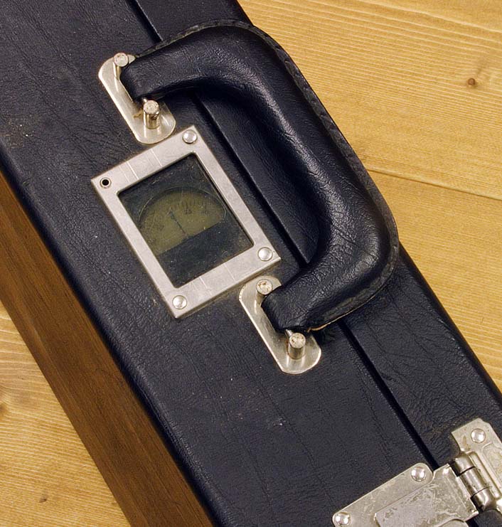
HRS-23M Beacon Locating System
This system is apparently intended for tracking or locating a small transmitter such as a “wire” worn by an informant or agent, or a beacon attached to a vehicle. General description from the manual, which is dated January 1978:
“The HRS-23M (or HRS-23) is a portable, battery operated, beacon receiver system operating in the 220-240 MHz frequency range. Through proper application, it will allow an operator to locate a compatible beacon transmitter by providing him with Left-Right direction and signal strength information. System operation is flexible since three modes of operations are provided – Airborne, Auto, and Portable. Most of the equipment necessary for each mode of operation is contained in two carrying cases provided.”
The manual includes instructions for mounting the system in a car or small aircraft, using a pair of vertical rod antennas. The receiver demodulates AM, and includes a BFO. The manual does not include schematics, repair info, or images of the inside of the unit. The “HRS” designation is likely an acronym for Homing Receiver Set/System.
Some of the main components of the HRS-23 system. The main unit in the center is a 6-channel HRR-23 receiver, with the HRD-23 homing device above. The 3 small rectangular objects on the upper-right are frequency selection modules. A vertical antenna is visible on the left, the second antenna is hidden under the foam. The black box on the right is the HRK-23 Test Fixture, which generates a simulated signal for setup and calibration. The button for opening the case on the left side is actually the receiver's gain control. Image courtesy of Bill Adams.
In a second case are various accessories that can be used in an auto or aircraft installation, including a pair of vertical antennas (HRN-23) and bases which are mounted on the roof of a car, or on the front hood of an aircraft. Image courtesy of Bill Adams.
A DF indicator is mounted under the handle. The false rivet in the upper-right is a push-button which illuminates the meter, while the rivet in the upper-left is an earphone jack. The meter is covered with a polarizing filter so that it is only visible when viewed directly from above, so that someone standing nearby would not be able to see the meter. Image courtesy of Bill Adams.
Induction Coil (Wire Tapping Device)
This device, marked "F-371 IndCoil", is an audio wire tap, most likely intended for telephone lines. It is an inductive pickup, so does not require any direct connection to the signal wire. This makes it much more difficult to detect, and does not interfere with telephone operation in any way. The model F-371 was sold by Fargo Company (and others), along with many similar devices in the 1950’s and 1960’s, for sale to law enforcement agencies. This particular one belonged to a TSD employee who died in 1968.
When clipped over the red wire on a traditional telephone line, and connected to a suitable preamp, it can efficiently monitor a conversation. Note that it is necessary to tap only one of the two signal wires - if both wires pass through the device, the signal is cancelled. The tap includes a square, closed armature that is opened by pushing a spring-loaded button. Two sides of the square have fine wire coils wound on them, connected in series.
The wire-tapping device. Pushing the black button on the right side causes the armature to open so that it can be clipped over a wire. The oblong aluminum portion is a separate impedance matching transformer, marked "3.2" (ohms) on the input, and "1200" on the output. It has a 1/8" plug on the input side, and a matching jack on the output side.
Unidentified Subminiature Audio Amp
The exact purpose of this device is unknown, however it is extremely similar to an early transistor hearing aid, but without a built-in microphone. It is a small aluminum clamshell box, about 2.5" long, containing a 3-transistor audio amplifier. It uses early Raytheon germanium transistors (one is a CK721 with a mid-1953 date code), and the stages are transformer-coupled. The required battery is about the size of an 'N' cell - there is a hand-written note inside the case lid saying that the battery is 2.6 volts. The output connector is a 2-pin hearing aid earphone connector. The input is a tiny 7-pin Winchester connector.
Three views of the sub-mini amplifier. The black component in the lower left, marked "3-21", is one of the 3 transistors. The color-coded resistors are 1/2 watt units (for size comparison).
Japanese-made Audio Amplifier
This device is another simple audio amplifier, but in this case it was made in Japan. The dimensions are 5-1/4" X 1-3/8" X 1-1/4", in a steel box with gray enamel paint. It uses two socketed Sony 2T65 transistors (similar to 2N214's), with R-C coupling between the stages and a transformer-coupled output. The electrolytic caps are made by Nippon Chemicon. The input connector is an unidentified type, about 1/4" in diameter with a center pin. The output is a 3-pin male mic connector, like those used with older C.B. and mobile radios. The output impedance is 600 ohms, and DC power input is 9V. The phenolic circuit board is hand-wired (not printed).
The inside of the lid and the inside of the box each are stamped "1". Since before WWII, Japanese manufacturing was in the habit of marking pieces with an 'assembly number', since many pieces were hand-fitted to each other. So, it is possible that this unit is a prototype.
The "Japanese amplifier", with the cover removed. The two gray objects are the Sony transistors. The input connector is on the right (not visible), and the output is on the left. The red and blue leads on the left are the power input. The white, blue and brown wires connect to the output connector, but are not attached on the other end.
Maico Hearing Aid
Maico is a commercial hearing aid brand that dates from the late 30's. The "Transist-ear" is one of their earliest solid-state models, using three CK718 transistors. This one has had its mic removed, and a 1/8" phone jack added in its place. It was obviously being used as a subminiature mic preamp, similar to the custom-made unit described above.
For much more information on this item, refer to https://www.cryptomuseum.com/covert/mic/maico/index.htm .
Front and back views of the modified Maico hearing aid. The added 1/8" phone jack is visible at the top.
Unidentified Battery Box
This unidentified battery box was machined from translucent black plastic, with phenolic inserts mounted from behind with small screws. It appears to accept two 30 volt batteries, and six 'N' cells. The box measures 5-5/8" X 2-1/2" X 7/8".
Assuming that the two large batteries are 30V each, and that each small cell is 1.5V; then the box could provide any of the following outputs: +60V (with or without a 300-ohm resistor in series), +30V, -1.5V (two cells in parallel), -6V, and -3V.
The battery box with the cover removed. In the center is a pair of contacts that are normally shorted, but when a plug is inserted through a hole in the case, the contacts open and are shunted by 300 ohms.
Home-made Surveillance Devices
Shown here are some devices constructed by the author, as an exercise in building various surveillance devices using 50's or 60's vintage components wherever possible.
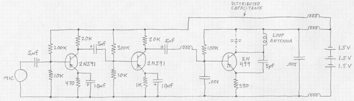
This is a "bug" transmitter, built as a working copy of the "book-spine transmitter" shown in Keith Melton's "Ultimate Spy" book (page 111 of the 3rd edition, page 103 of the 2nd edition, page 83 in the 1st edition). From the bottom upward, the major components are: mic element, 1st audio stage, 2nd audio stage, RF oscillator, and 3 batteries. The transistors are 2N591 (two, audio) and 2N499. The antenna is a PC trace that goes around the perimeter of the board, thus forming a loop. This loop is also the "L" in the RF tank circuit. The "C" in the tank is the distributed capacitance of the components. The frequency is in the 80 MC range. RF power is estimated to be 3 to 4 mW. Schematic of the "book-spine transmitter"
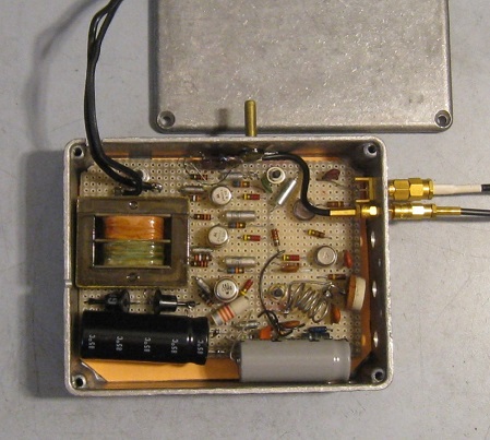
Shown here is another home-made surveillance transmitter that is functionally much like an ST-3. Features include: Built-in AC power (like the ST-2A and ST-3), tunable from about 70 to 90 MC FM, and all solid-state with early 1960's transistors. The antenna connector is an SMA, the mic input is an SMB. The three transistors just to the right of the transformer are the audio stages; while the two on the right are the RF oscillator and buffer stages. Schematic of the home-made transmitter
A Commercial Surveillance Receiver
A Swintek Q-6R surveillance receiver from the 1980's, as used by police and private detectives. The receiver itself supports up to 6 crystal-controlled channels, and includes a relay output for controlling a tape recorder. The antenna is mounted inside the lid of the case. The two smaller black boxes on the right are transmitter units, one with a lapel mic connected. Author's collection.


