(c) 1999,2024 Peter McCollum
Beacon transmitters were used by agents to signal the location of a desired air drop or pick-up. Some of the early models operated in the low HF band (aka MF), so that aircraft navigation equipment could be used to track the signal.
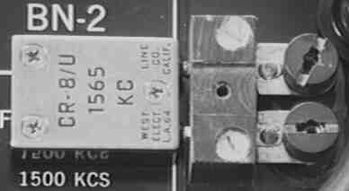
The RT/A-3 Transmitter, a part of the BN-2 (aka HRT-4)
This beacon transmitter was available prior to October 1959, and was developed by TSS/TSD, rather than the Commo group. The RT/A-3 is based on a 'standard' RT-3 transmitter, but with several modifications (see the list below). The beacon system was original known as the BN-2, but by early 1961 the nomenclature was changed to HRT-4 (Homing Radio Transmitter). In the field, it was commonly powered by a GN-58 hand-crank generator. The 1959 cost was $198, including an antenna.
Other beacons of the time period include the HRT-1 and HRT-2, which are solid-state and operate from mercury batteries. These early HRT-series beacons were used extensively in the Far East, “…where vast regions are unmapped, and radio beacons are the one and only method of finding the drop area” [CIA memo, March 1961]. The HRT-2 was proposed as the replacement for both the HRT-1 and BN-2, effective in January of 1962. Initial production HRT-2 units were scheduled to be delivered in January of 1961. Tests with various antenna systems were conducted in September 1961, using a C-47 aircraft with an ARN-6 radio-compass. Antenna options included a 16-foot whip, a balloon-supported 150-foot wire, and an AN/A-42 antenna. The HRT-1 was apparently a commercial product, the “Wesmont Terminal Navigation Beacon, Model 4”, otherwise known as a “Wesponder”.
The following modifications to a standard RT-3 are observed on the RT/A-3:
· The tuning chart plate has been replaced by a plate that reads "RT/A-3 PART OF BN-2 TUNING RANGE 1500-1800 KC". The original RT-3 ID label is still there.
· The band switch has been removed, and replaced with a screw that plugs the hole (to keep the unit watertight). Inside, all of the bandswitch components are gone.
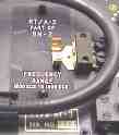
· A fixture has been added to the FT-243 crystal socket: it allows a crystal to be installed in the horizontal position, laying across the BN-2 label plate. The original crystal socket is still usable, and the second socket (for crystals with wider-spaced pins) is still there, also. Because of the crystal-socket modification, it could have been delivered to the field with a crystal already installed with the lid in place.
· The antenna tuning cap has been replaced by a dual-section 365 pf unit, with both sections wired in parallel for a total of 730 pf. The cap looks like a commercial broadcast radio type, with a compression trimmer on each section. To mount the cap, three holes were drilled and countersunk in the front panel. The original watertight shaft bushing has been mounted upside-down on the top of the panel, and there is a rubber washer under it. This allows everything to remain watertight, but allows the new capacitor to mount close to the panel. However, since the shaft bushing is mounted on the "wrong" side of the panel, the antenna tuning knob is now higher above the panel than the original.
· There is a schematic (marked "RT/A-3 TRANSMITTER") glued to the inside of the case. On one RT/A-3 unit, many points in the schematic have a small hand-drawn check-mark next to them - it's as if the technician was checking off the modifications as he did them, then he glued the schematic in the box when he was finished.
· The ant. current indicator is a #43 lamp, instead of a #47 (this is indicated on the schematic, also). The lamp's parallel resistors are a much smaller value than the original. Most of the rest of the circuit is the same - although the plate-tank is a toroid transformer (two separate windings), and the oscillator tank is also a toroid (single winding). These new toroids are about 1" diameter, and are mounted on plastic standoffs with nylon screws.
· Because of the change in the antenna current lamp circuit, it only glows when the antenna impedance is low (around 20 ohms or less). This probably indicates something about the intended type of antenna for the RT/A-3 (perhaps a bottom-loaded vertical whip?).
· The outside of the case and lid has a 2"-wide yellow stripe painted on it.
· The original code-key is there, and works normally, although the units were adjusted so that the contacts were closed all the time. So, the unit would transmit a carrier as soon as it was powered up. With the key 'locked down', it would be easy for a single person to set up and operate the transmitter with a GN-58 generator.
An R&D Lab report in March 1959 mentions a “DZ Location System, BN-1”, based on a “short pulse radar unit”. This project was not pursued because of the very limited range.
RT/A-3 transmitter. Note the missing bandswitch control, the modified crystal socket, and the yellow stripe on the case.
Close-up view of the RT/A-3's modified crystal socket, with a crystal installed.
Another style of RT/A-3 modification (probably later).
Radio Set AN/URC-4
The URC-4, often referred to as a “pilot's rescue transceiver”, was sometimes part of an agent's equipment, to use as a beacon for air-dropped supplies [ref 105, 108, 109, 111, 114, 115, 125, 129, 133, 144]. The standard URC-4 was modified to mount on a camera tripod, and the dipole antenna was replaced with a ground plane, and tuned for a frequency other than the standard 121.5 MC [ref 111]. Since the antenna was a ground plane, there was a strong “null” in the signal as the aircraft flew over, to indicate when to make the drop. Agency testing of this system was performed with C-47 aircraft with AN/ARA-8 homing equipment. Two criticisms of the system: the specialized battery could be difficult to obtain in the field; and users were nervous about the long and continuous transmit time that was required, plus the super-regenerative receiver that radiated a signal as well. The URC-4 cost was $178 in 1956.
The RS-54 was the replacement for the URC-4, beginning in early 1964. Unit cost was $480 each.
The URC-11 was also used in the beacon role when it became available in early 1957. It was less than half the size, because of employing transistorized audio stages. Agency testing was performed in January 1957, along with the SARAH beacon and another system.
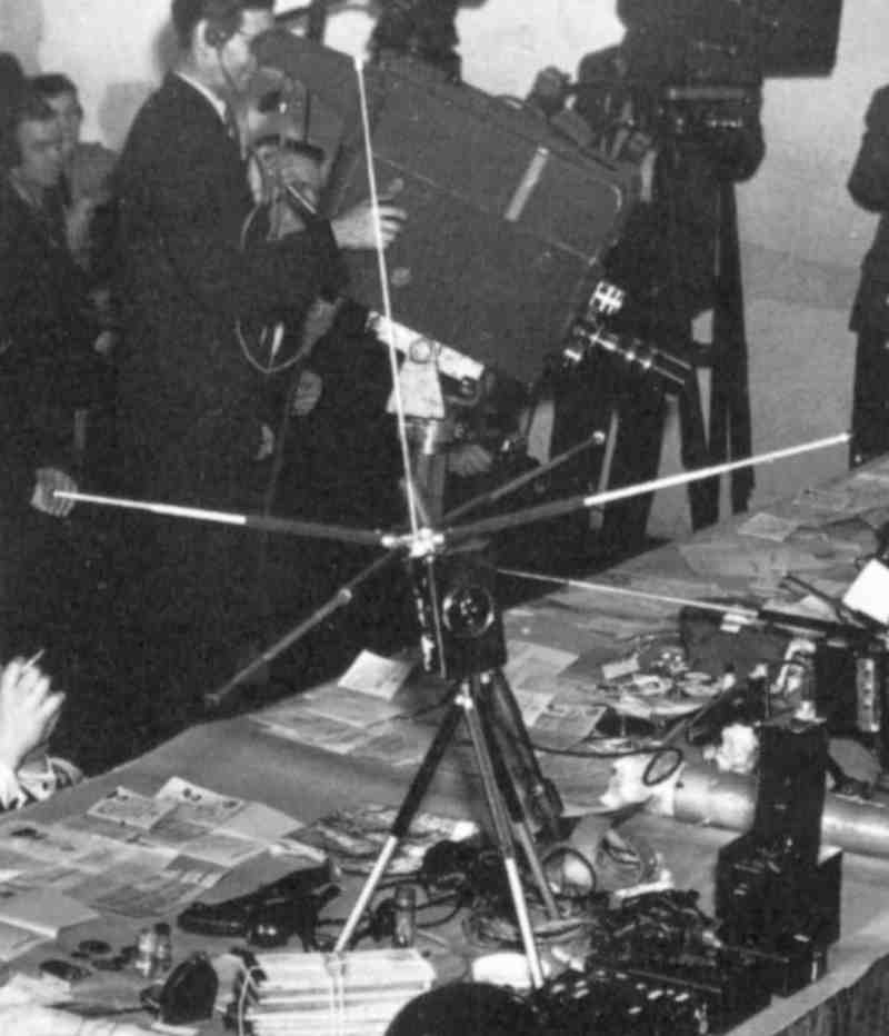
The picture below is from a portion of a picture of a Soviet press briefing in 1957, showing captured spy hardware. The item in the center is a URC-4, with a non-standard groundplane antenna for use as a beacon, and is mounted on a small tripod. In the foreground appears to be an RS-6 set.
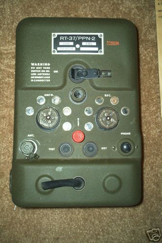
RT-37/PPN-2 Beacon “Rebecca-Euraka”
The PPN-2 is a transponder beacon, used primarily for marking a ground location for aircraft to use as a homing signal. The PPN-2 Beacon, and the aircraft-mounted APN-2 interrogator, were known to the British as the "Rebecca-Eureka" system. See "Wireless For The Warrior, Volume 4" for details on the system.
The CIA used the PPN-2 on some missions until at least late 1952 [ref 106, 111, 112a].
A “Eureka” unit. Images courtesy of the late Bill Howard.