
(c) 2004,2026 Peter McCollum
ELINT and SIGINT - Electronic and Signals Intelligence, Surveillance, and Telemetry
ELINT and SIGINT, or Electronic Intelligence and Signals Intelligence, involve monitoring the transmissions of the opposition, and studying the received signals to learn not only their message content, but also to learn the capabilities and limitations of the technology. For example, a major ELINT activity during the Cold War was to monitor Soviet missile tests, and try to determine the capabilities of the missiles, their payloads, and the radar systems used to track them. Some very important data is acquired by intercepting various radio signals related to a missile launch. These signals include rocket telemetry, radar pulses, and also the 'human' communications that may be discussing the launch.
Several companies made VHF and UHF surveillance and telemetry equipment for various government agencies during the 1950’s and 1960’s. CIA documents include references to the following receiver models: Communications Electronics Inc. (CEI) models 901 and 904; and Nems-Clarke models 167-J2, 1302A, 1306, 1501, 1702A, and 2801.
An interesting 1961 article from the CIA’s internal journal “Studies in Intelligence” gives some insights into the ELINT business, as applied to the “Space Race” of the 1960’s. See the article here: Intelligence for the Space Race
See Terry O'Laughlin's site for much more info on these types of equipment.
Surveillance Receivers
These receivers were used by CIA to monitor listening devices (‘bugs’), and in the R&D Lab to support the development of various surveillance devices.
The Nems-Clarke model 1306, as shown in the manual. Released in 1961, it tunes 30-260 MC in two bands, with separate front-end tuners for each band, and four separate IF strips providing bandwidths of 10 KC, 300 KC, 500 KC, and 1 MC. Click HERE for the 1306 manual.
An example of the Nems-Clarke 1500 series Surveillance Receivers. Models include the 1501, 1502, 1503, 1509, 1510, 1511, and 1512. Most models cover 55-260 MC, but some are 40-180 MC. The first I.F. is 21.4 MC, which makes them compatible with panoramic adapters used by other brands, such as CEI and Watkins-Johnson. Most models use a 6J4 as the RF front-end; but in some models the 6J4 is preceded by a 416B planar triode for better sensitivity and/or noise figure.
Aerospace Telemetry from the 1950’s to early 1970’s
In this sub-section, I have chosen to go somewhat beyond the “spy radios” theme, to give a broader coverage of aerospace telemetry. I find the topic very interesting, but it is barely mentioned in most sources that are oriented towards historic radio equipment.
As mentioned at the top of this page, the CIA has a specialized interest in telemetry signals emanating from aircraft (typically rockets and satellites) launched by other countries. In the time period of interest (up until about 1970), telemetry did not yet include sophisticated encryption schemes, so many things could be learned by intercepting and analyzing the signals.
Telemetry Signals
The term ‘telemetry’ (in the context discussed here) refers to a signal that carries data transmitted by a vehicle back to a receiving station, where the data can be analyzed and stored. More specifically, the data is from a rocket, missile, aircraft, or satellite. A large rocket or spacecraft is likely to have dozens or hundreds of parameters that need to be monitored from the ground – temperatures, pressures, velocities, voltages, etc. See the two examples in the image below. Each parameter may have a different bandwidth, depending on what type of sensor is employed – some values change slowly, while others change suddenly. But in general, most telemetry data in this time period had a bandwidth that was in the DC to audio range.

Pictured here are examples of the number and type of telemetry signals that may be required. On the left is the measurements from stage 2 of a Saturn V rocket in 1968 (stages 1 and 3 had their own additional telemetered measurements). On the right is a Telstar satellite in 1963, being used for a solar radiation experiment.
IRIG Standard Frequencies and Subcarriers
Standards for telemetry spectrums and equipment began to appear in 1948. Beginning in the 1950’s, an organization known as the Inter-Range Instrumentation Group (IRIG) was producing “Document 106, Telemetry Standards”. The 1960 version includes definitions for RF frequencies, subcarriers, multiplexing schemes, pulse-code modulation (‘PCM’, early digital encoding), and magnetic tape recorder/reproducer standards.
An earlier version of the telemetry band covered 216-245 MC, but by 1960 the upper limit was expanded to 260 MC, with a total of 62 frequency assignments, as shown in the table below.

Telemetry frequencies defined by the IRIG-106 standard by 1960. There was also a defined telemetry band from 1435 to 1535 MC, and also from 2200 to 2300 MC. This table is from the 1965 standard.
To allow more than one parameter to be conveyed on a given RF frequency, subcarriers were defined, as shown in the table below. The next sub-section discusses this in more detail.

Subcarrier bands defined by the IRIG-106 standard.
The Evolution of Telemetry Standards
The first telemetry standards were produced by the Research and Development Board (RDB) of the Department of Defense in 1948, which had responsibility for missile systems development. The RDB included a ‘Working Group on Telemetering’, which produced the first Standard. In March 1952 the RDB was replaced by the Inter-Range Instrumentation Group (IRIG). Following are the important milestones in telemetry standards.
RDB Working Group standard approved (December 1948). A basic FM/FM system was defined. It included only six subcarrier channels.
MTRI 204/6 (November 1951). RF channels are 217.550 MC and 219.450 MC, with a maximum deviation of +/- 125 KC. In addition, 225-230 MC can be used on a “non-interference basis only”. There are now 18 subcarriers defined, from 400 CPS to 70 KC. Receivers are recommended to support 215-235 MC with a 500 KC bandwidth, in anticipation of wider band allocations in the future.
IRIG is formed (March 1952).
IRIG Recommendation 102-55 “Telemetry Standards for Guided Missiles” (July 1955). The first IRIG telemetry standard. The RF band is 216-235 MC, but specific frequencies are not yet defined (users are expected to coordinate exact frequencies with the missile range). The subcarriers and most other details are unchanged from MTRI 204/6.
IRIG Recommendation 103-56 “Revised Telemetry Standards for Guided Missiles” (October 1956). Adds more detail related to PDM/FM systems and FM/FM commutation. The subcarrier bands now include five optional channels with +/- 15% deviation.
IRIG Recommendation 101-59 “Frequency Utilization Parameters and Criteria” (January 1959). Within 216-225 MC, channels are every 0.5 MC, on a non-interference basis. Within 225-260 MC, a list of 44 specific frequencies are now defined. Bands of 1435-1535 MC and 2200-2300 MC are also defined. This document became “Appendix I” in IRIG Standard 106-60.
IRIG Standard 106-60 “Telemetry Standards” (November 1960). The first comprehensive Range Telemetry System standard, because it encompassed several areas that were previously in separate documents, such as magnetic tape recording and PCM. Updates continue to be published periodically.

An original copy of Standard 106-60 (revised 1962). Author’s collection.
Modulation and Multiplexing Methods
It is not feasible to dedicate an RF channel to each measurement, since there are typically far more measurements than channels, and each RF channel requires significant hardware on both ends of the communications link. However, since the bandwidth of the typical measurement is in the low audio frequency range, and each RF channel has a 500 KC bandwidth, the use of multiple audio sub-carriers is a practical solution. This technique is known as ‘Frequency Division Multiplexing’.
In the simple case, each measurement value frequency-modulates a separate audio sub-carrier oscillator (SCO), several of those SCO outputs are mixed together, and the resultant complex audio signal frequency-modulates the RF carrier. In the ground station equipment, the detected complex audio signal is presented to multiple ‘sub-carrier discriminator’ circuits, each tuned to a specific sub-carrier’s base audio frequency. The outputs of the discriminators represents the various measurement values in ‘real time’. This system is known as “FM/FM”, because a frequency-modulated subcarrier is used to frequency-modulate the carrier.
The following four diagrams below are from “Aerospace Telemetry”, by Harry Stiltz (editor), 1961.

The simple frequency-division multiplexing described above is still not practical when there are hundreds of measurements. However, many measurements are nearly DC values (very low BW), so a continuous real-time path is not necessary. Therefore, it is possible to ‘time-share’ a single SCO input across many measurement values. A device known as a ‘commutator’ selects each of the measurements in turn, and applies it to the SCO. For example, perhaps 20 measurements are sampled individually for 50 mS each, then the cycle repeats, allowing a complete set of 20 measurements to be sent every second. This commutation scheme is relatively simple to implement in the aircraft, although there is some complexity in the ground station. Early commutators consisted of a motor driving a multi-position rotary switch. By the early 1960’s, electronic commutators were common, eliminating the need for mechanical parts. See the diagram below.
The 1965 IRIG standard describes two main variations on the time-division multiplexing scheme. One is pulse amplitude modulation (PAM), where each sampled measurement becomes a pulse with an amplitude proportional to the measured value. The other method is pulse duration modulation (PDM), where the amplitude is constant, but the width varies according to the measured value. Both PAM and PDM have certain advantages/disadvantages related to channel bandwidth, hardware complexity, etc. Refer to the diagrams below, which show a mechanical commutator being used to sample the measurements.
A third major system described in the IRIG standard since 1960 is pulse code modulation (PCM). Each measurement becomes a binary-encoded value, which is then sent serially. The standard allows for variations in word length, bit rate, optional parity, etc. By the late 1960’s, improved solid-state circuitry was allowing PCM to replace most types of ‘analog’ telemetry. For example, during the Apollo program, the Saturn V rocket stages used primarily analog telemetry through Apollo 10, but for Apollo 11 in mid-1969, most of those measurements had been converted to PCM.


Telemetry Receivers
With the rise of the aerospace industry in the 1950’s, several manufacturers began making receivers with features that are specific to telemetry signals. Perhaps the most prominent company, especially in the early years, was Nems-Clarke. See Terry O'Laughlin's site for much more info on the history and equipment of the various companies.
A typical telemetry receiver was capable of tuning any of the IRIG channels from 216-260 MC, supported a very wide FM bandwidth (compared to a common communications receiver), and had multiple meters for parameters such as FM deviation, tuning, and signal strength. Some models, especially starting in the mid-1960’s, supported plug-ins for wider frequency coverage and other options.
Below are details of some specific telemetry receiver models.
Year 1947: Clarke Instrument Corp. model 167-D

Clarke Instrument model 167-D, serial # 124. Tunes 175-260 MC. The 167 series, first built in 1947, was the first telemetry receiver product from Clarke Instrument Corp., before they became a division of NEMS in January 1951, as “Clarke Instruments division of National Electrical Machine Shops”. [Note that NEMS was the manufacturing contractor for the RS-1 agent radio set, after initial production done by RDR.] This particular unit was made in the middle of 1950. There were several variants to this model, suffixed by letters E, F, G, J, J-1, and J-2. I have not found any documentation for this “D” variant, but it seems to be essentially the same as an “E” version. The “F” and “J” versions tune a wider range of 55-260 MC. But it is interesting to note that all models use the same Mallory Inductuner (a variable spiral inductor) in the tuner. In the 175-260 MC models, there is a mechanical stop that makes the lower frequencies unavailable, and a few component values are different as appropriate to optimize the performance for the higher frequencies. The IF bandwidth for the “E” and “F” models (and probably this “D” model) is 500 KC, while the “G” and “J” are 300 KC. The controls are (from left to right): Audio Gain, Power, Automatic Frequency Control, Standby/Operate, and Tuning. The meters are Tuning and Signal Strength. The 167 was initially sold primarily for scientific and medical purposes, but later became one of the first important receivers used to receive missile telemetry. Click HERE for an inside view of the 167-D . Author’s collection.
Year 1955: Nems-Clarke model 1670-E

Nems-Clarke model 1670-E, serial # 520. Tunes 175-260 MC. This particular unit was made in the latter part of 1956, and the branding is now ‘Nems-Clarke’ after Allen Clarke became president of NEMS in January 1955. So, the 1670 is likely the first model to bear the “Nems-Clarke” name. As with the previous model 167 (see above), there are letter-variants of E, F, G, and J. Other than the differences visible in the front panel, the 1670-series is nearly identical to the 167-series. Note that “1670” is merely “167” with a “0” added. Within about 2 years after the 1670-x series, we see the models 1671, 1672, 1673, and 1674. These four models are again nearly identical to the four ‘lettered’ versions of the 1670. But now the important difference is that Nems-Clarke has become a division of Vitro Corp. since September 1957. It appears that the new model numbers (with no letters appended) are primarily a re-branding of the 1670-series, and the manuals for the new models include the Vitro logo. So, all of these receivers mentioned so far are all minor variations of the same basic design seen in the model 167 since 1947. Click HERE for an inside view of the 1670-E . Click HERE for the 1671/2/3/4 manual . Author’s collection.
Year 1956: Nems-Clarke model 1400
Nems-Clarke model 1400 Telemetry Receiver, serial # 238, made in 1957, the year that Nems-Clarke became part of Vitro Corporation. The model 1400 is first seen in the 1956 catalog. Tunes 215-245 MC, crystal control only, and this model was used extensively in the Atlantic Missile Test Range. It is the second major receiver design following the models 167 and 1670. The 1400-series is considerably more complex than the 167/1670 series models, adding features such as a higher-performance front end, crystal control, dual IF bandwidths, and a deviation meter. A 1961 catalog includes various 1400-series models, but no longer this particular model. Click HERE for the 1400 manual. There were at least 17 variants in the 1400-series (23 if letter-variants are included). Controls are, from left to right: audio gain, I.F. selector (100 KC or 500 KC), deviation meter range select (25, 75, or 150 KC), 2nd L.O. frequency adjustment, and front-end tuning. The meters indicate frequency deviation, tuning, and signal strength. The power supply filter caps, and many of the tubes, are dated 1957 in this example. Crystal control has become a common feature by now, perhaps because of the growing use of standardized frequencies, as with the IRIG standards. This particular unit came with a crystal oven to receive 232.9 MC, and is believed to have been used by Martin-Marietta in Colorado Springs in 1965-66, to monitor the LES-3 satellite beacon, which broadcast on that frequency. The deep blue front panel is unusual, and likely a customer-requested feature. Click HERE for an inside view of the 1400 . Author's collection.
Year 1957: Nems-Clarke model 1401A

Nems-Clarke model 1401A, serial #206. The model was first available in 1957; this example is from 1958. The 1401A seems to represent a transition between the 1400 and the 1412, and Nems-Clarke is now owned by Vitro Corp. since 1957. The internal circuitry is almost identical to the 1400, except that the upper limit of the tuning range has expanded from 245 MC, up to 260 MC. The front panel is the same as the model 1412, but the knobs are still the style used on the 1400 and the earlier 1670. A model VF-1400A transistorized VFO option is shown installed in the crystal socket (otherwise, it is crystal control only). Author’s collection.
Two other models from the 1400 series - a model 1412 (left, nearly identical to the 1401A shown above, except for the style of knobs), and a model 1433. These models are seen in a 1961 catalog. Click HERE for the 1412/1432 manual.
Year 1963: Defense Electronics Inc. model TMR-5A
Defense Electronics Inc. (DEI) model TMR-5A, serial # 408. DEI was formed by former employees of Nems-Clarke in about 1960. Nine RF plug-ins (on the right) were available to cover the range from 55-2300 MC (the one shown tunes 55-260 MC). The “Video Unit” plug-in (on the left) supports at least 11 different IF amplifier modules, and 4 demodulator modules; one of each type is installed in the plug-in’s chassis. The text in the black rectangular windows shows which modules are installed (in this case, “.3/.75” and “WIDE BAND”). Other DEI receiver models include TMR-2A, TMR-6, TMR-21, TR-711, and TMR-74A; plus the 2074A which is a Nems-Clarke model (essentially a dual 1037 with a diversity combiner included). Per Terry O’Laughlin, DEI was sold to an investor in 1969, and went out of business soon after. Author’s collection.

Another of the nine RF plugins available for the TMR-5A receiver chassis. This one, a TMH-E5, tunes only the VHF telemetry band of 215-265 MC, but supports a front-panel crystal in addition to a VFO. Author’s collection.
Year 1962: Nems-Clarke model 1037 series
The model 1037 series represents one of the last models from Nems-Clarke before the Vitro Electronics telemetry receiver line was sold to DEI in 1968. It was available starting in 1962, for the Mercury and Gemini space programs. The 1037 series (with letter suffixes from ‘A’ to ‘G’) supports plug-in modules for the front-end tuner and the discriminator. With various tuners, the frequency range is 55 to 2300 MC. This example is a 1037F-39, serial # 890, made in 1966. The technology is a mix of Nuvistor tubes (in the RF tuner only) and transistors. Click HERE for a block diagram, and notes on the functionality of the rear-panel connectors. The blank panel in the upper-right is for an optional spectrum display unit (pictured below). Author’s collection.
It is believed that the “-39” after the model number represents a variation in the base design requested by a customer. An example 1037F with no variation number (serial #860) appears to have no special features. This 1037F-39 pictured above (serial #890) includes an extra internal module, a TSC-301, which is a Schmitt trigger circuit for the received signal level. It outputs a voltage to a rear-panel connector whenever the signal level is above a threshold. The purpose was possibly to control a recording device or similar.

The optional SDU-364 Spectrum Display Unit, mounted in a 1037F chassis. Author’s collection.

This is another 1037F, but a “-38” variation, serial # 877. Note the lack of a “Video Filter” switch in the lower-left area of the panel. The RF tuner is also unique; it is marked on the rear panel “RFT-101D-2”, and has the following changes: 1) The crystal oven supports two crystals instead of one. 2) The selector switch chooses one of the crystals, or the VFO option. 3) Two specific IRIG channels are permanently engraved on the panel, and an alternate pair of channels has been added with stickers. 4) There is an indicator lamp next to each of the 3 selections. The lamps are NOT controlled by the switch; rather they are wired through the plug-in’s connector into the main chassis, and finally to a Winchester connector on the back panel of the 1037F. So an external circuit is required to illuminate the lamps. This setup was perhaps used in a ‘test harness’, where a separate system illuminates one of the lamps to tell the human operator which channel to select for the test. See the “TEST SET” marking in the image below.
Research shows that the 3 specific IRIG channels (229.9, 227.2, and 231.9) marked on the panel were among the 11 RF channels used by Apollo 9 and 10 to carry telemetry from the 1st and 2nd rocket stages. Since there were 62 available channels, it is probable that it is NOT a coincidence that this receiver is marked with 3 of the Apollo channels. So, it is believed that this receiver was used in support of Apollo 9 and/or 10. Author’s collection.

Comparing the RFT-101D-2 with a ‘standard’ RFT-101A.

These markings are on the rear panel of the 1037F-38. “GD/POMONA” refers to the Pomona division of General Dynamics. The references to “TM 6-239 966” and “MK 499 MOD 0” are unknown.
Year 1972: Microdyne model 1100-AR
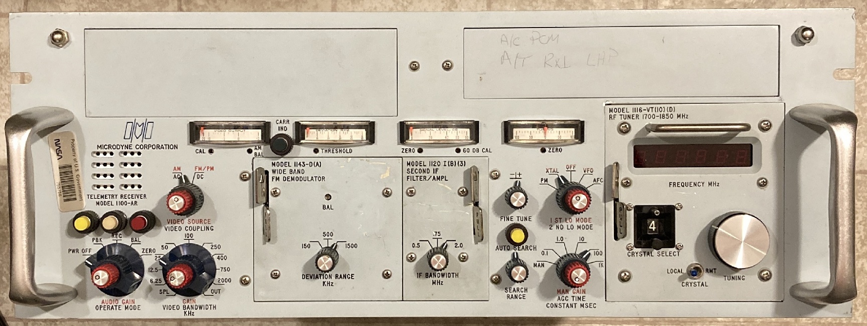
This Microdyne 1100-AR serial #3418 was made in 1989, which is likely near the end of production for this model, which started in 1972. It seems extraordinary that it had such a long lifetime. Like the Nems-Clarke 1037 series and others, it features plug-ins for tuners, demodulators, etc., but with certain core features built into the chassis. Most of the telemetry applications were in the L-band and S-band microwave frequencies, because the original VHF band was no longer allocated for telemetry since 1970. The technology no longer includes any vacuum tubes, even for the microwave-band tuners. The circuitry includes some integrated circuits that were available in 1972, such as early op-amps. Author’s collection.
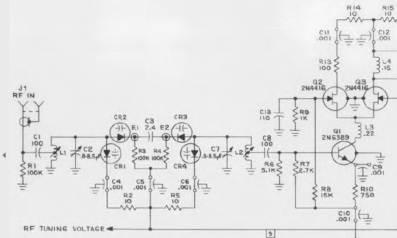
An interesting feature of the Microdyne 1100 is that some of the plug-in tuners support “remote tuning”. This is accomplished with a simple control voltage, driving an array of varactor diodes in various parts of the circuit. The tuning voltage is brought out to a connector on the back panel. Shown here is the input pre-selector on a tuner. The 1st local oscillator has a similar varactor array. So, these tuners have no variable capacitors or inductors – the VFO tuning control is a simple multi-turn potentiometer.
Transmitting Equipment
As shown in the diagrams above, some major components of an airborne telemetry system are sensors, a commutator, subcarrier oscillator(s), and a transmitter. The transmitter is a straightforward design, with a crystal oscillator, typically two or more multiplier stages, and a power amplifier. Frequency modulation is achieved by “pulling” the crystal with a reactance modulator, or by using a VCO that is mixed with the crystal oscillator output.

A Telechrome model 1472-B telemetry transmitter, from the mid-1950’s. Four sub-mini tubes: reactance modulator, crystal oscillator, doubler, and amplifier. Operates from 6.3 VDC for the filaments, and 200 VDC for the plates. The connector pinout is the same as the Telemet, listed below. Telechrome also manufactured color television equipment. Author’s collection.

A Telemet model 1483-A14 telemetry transmitter. This model was released by Telechrome in late 1959, but Telemet purchased Telechrome in about 1962. Operates from 28 VDC for the filaments, and 180 VDC for the plates. Power output is 2.5 watts. Connector pinout: B – B+, D – filaments, E – Modulation input, H – Ground. Author’s collection.

A telemetry transmitter, made in 1969, all solid-state. This example is a Dorsett model TR-320F, operating at 316.5 MC. The multi-pin connector includes inputs for +24V power, an enable input, and an FM input with a deviation of about 7 KC per volt. The total power input is about 1.1W, so it’s possible that it was used with a linear amplifier for higher output. It is unknown what the application was, given that it operates outside the IRIG telemetry band. Author’s collection, kindly provided by Terry O’Laughlin.
A subcarrier oscillator (SCO) is simply an audio oscillator that can be linearly frequency modulated by a control voltage. The typical design is a multivibrator oscillator (with VCO capability), followed by a bandpass filter to reduce harmonic output. The most common FM deviation is +/- 7.5% with an input from 0 to 5 volts. During the 1960’s, the form-factor, connector (DB-9), and pinout was standardized across various makers. A spacecraft telemetry “package” would include a chassis with positions for several (or many) SCO’s, driving one (or several) FM transmitters.
DB-9 connector pinout:
Input, 0-5 V.
(-) DC power in.
NC
Output Test (same as test point on the top panel).
Output (adjustable via top-panel trimmer).
Chassis.
(+) 24V DC power in.
NC
NC

Examples of SCOs (subcarrier oscillators), from various manufacturers. In the lower-left is an EMR model 54A, pictured in more detail below. All other examples employ a male DB-9 connector with a common pinout, except for the older DCS model in the lower-right, which has a unique pinout. The Aydin model in the upper-right is relatively modern – it was made in 1988, but follows the form-factor and pinout of the older models.

The internals of a LaBarge SCO. Author’s collection.

This is an earlier SCO from the mid-1950’s, a model 54A, made by Electro-Mechanical Research (EMR). It contains four sub-mini tubes; their function is likely two operating as a DC amplifier, and two as a multivibrator. The large cylindrical object is a passive low-pass output filter. Note that the connector is an “octal-style”, but with 9 pins. The pinout was standardized as follows: 1 – B+, 2 – Filament, 3 – Filament, 6 – Modulation input, 8 – Output, 9 – Ground. Author’s collection.
Telemetry Signal Processing
A ground station would typically require a number of subcarrier discriminators to separate the multiple audio channels found on each RF channel. Several manufacturers made this equipment, usually consisting of a number of plug-in modules in a horizontal rack shelf. Below is pictured an example made by Electro-Mechanical Research, which was one of the more popular brands during the 1950’s and 1960’s.

The larger of the 3 pieces (210A) is the main part of the discriminator. The 2nd piece (210B) mounts inside the 210A and determines the IRIG subcarrier frequency. The 3rd piece (210C) is a low-pass filter, chosen according to the bandwidth of the associated sensor on the spacecraft.

A better view of the EMR 210B and 210C modules. Author’s collection.
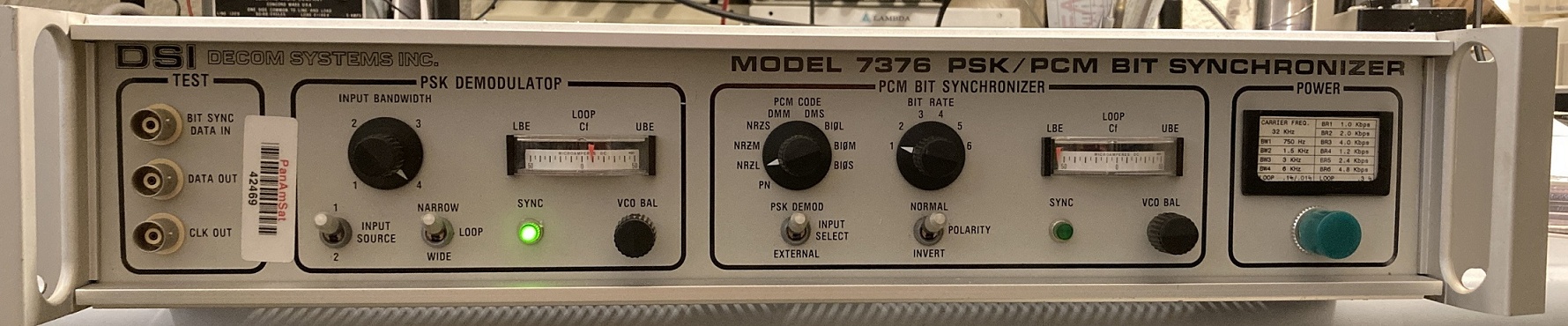
A Decom Systems Inc. model 7376 PSK/PCM Bit Synchronizer, from the late 1980’s. It processes the video output from a telemetry receiver, recognizes a phase-shift-keyed (PSK) modulation of PCM data, then performs bit synchronization to output an NRZ serial data stream. This example uses a 32 Khz carrier with six selectable bit rates from 1 kbps to 4.8 kbps. Author’s collection.
The Evolution of Nems-Clarke Branding
The image below shows approximately how the Nems-Clarke brand evolved over time, as shown on equipment ID tags.
Row 1: Clarke Instrument Corporation. Late 1940’s.
Row 2: Clarke Instruments division of National Electrical Machine Shops, Inc. 1951 through 1954.
Row 3: NEMS-CLARKE, Inc. 1955 to 1957.
Row 4: NEMS-CLARKE Co., a division of Vitro Corporation of America. 1957 to about 1962.
Row 5: NEMS-CLARKE, product of Vitro Electronics. From about 1962 to 1967.
Row 6: NEMS-CLARKE, product of Defense Electronics, Inc. Circa 1967.
Row 7: Defense Electronics, Inc., Circa 1963. Defense Electronics, Inc. producers of DEI and NEMS-CLARKE equipment, Circa 1967. Defense Electronics division of DEI Industries. Late 1960’s (perhaps 1969, when DEI was sold to an investor).

Receiver Test Equipment / Accessories

The HP-202J Telemetering Signal Generator. A rather precise and stable oscillator that tunes 195-270 MC, to cover the entire IRIG VHF telemetry band. It supports FM or AM modulation, internal or external, with calibrated FM deviation up to 300 KC. The internal modulation has 8 selectable frequencies, 6 of which are IRIG standard subcarrier channels (the other two, 50 Hz and 100 Khz, are intended for channel fidelity measurements). Originally designed by Boonton Radio, which at this time (mid-1960’s) had become a subsidiary of Hewlett-Packard. Author’s collection.
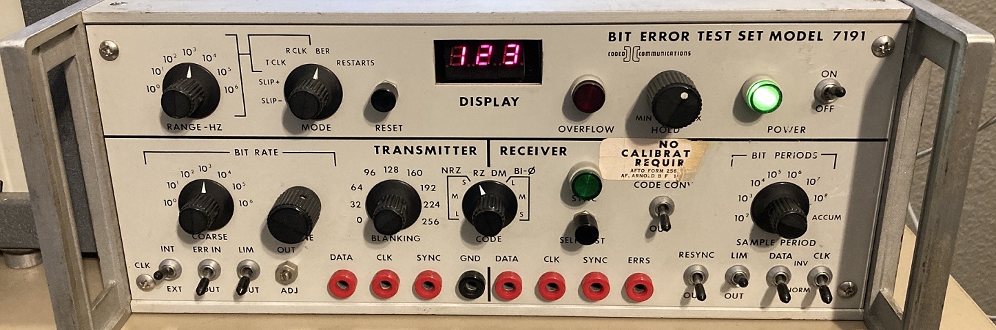
A Bit Error Test Set (“BERT”) made by Coded Communications in 1975. Used to evaluate the quality of PCM telemetry links. The “Transmitter” portion generates a pseudo-random serial bit stream, in various formats, using a Linear Feedback Shift Register (LFSR) at a rate adjustable from 1 bit per second to about 1 megabit per second. The “Receiver” portion compares the incoming data with the expected data, and counts the number of errors (and other parameters). The manufacturer apparently made equipment for ‘DECOM Systems’, and there is a patent number for the design assigned to Data-Control Systems in 1973. The circuitry includes about 120 TTL IC’s from the 7400 series. Author’s collection.
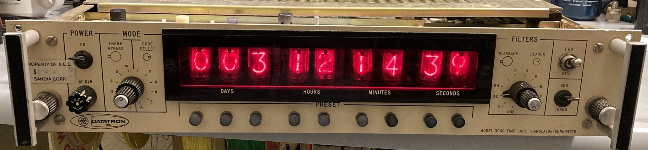
A Datatron model 3000 Time Code Translator/Generator, made in 1969. Telemetry signals typically need to be time-stamped, for recording on tape (see below) or on a paper strip-chart recorder. This device can generate IRIG standard time-code signals for use by other equipment in a ground station; or can decode and display time-code signals, such as from a tape playback. As a decoder, it supports six format variations (IRIG-A, -B, -C, -C1, -E, and -E1). As a generator, it can output IRIG-A, IRIG-B, and “Slow Code”. The latter is used for writing BCD timing marks on a strip-chart recorder, so the bits are output slow enough that a recorder pen can follow it. The circuitry in the Datatron 3000 includes several dozen DTL chips, plus various analog parts. By 1974, an almost identical unit was being made with LED displays instead of Nixie tubes. The brand seems to have started years before as Electronic Engineering Co., in 1963 making a computer time clock which they called a “Datachron”. Sometime later, the company brand changed to “Datatron”. In about 1968, the “Datatron” brand began to transition back to “Datachron”. Subsequent model numbers included 3150, 3170, 3200, and 3270. Author’s collection.
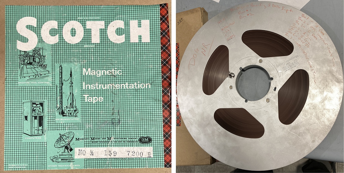
Telemetry data was typically recorded on tape, so that the data could be analyzed later. Technology in the 1960’s did not allow for very much “real time” data processing. Shown here is one common type: half-inch tape on a 14-inch reel, with 7 tracks of data, moving at 30 inches per second. One of the tracks would typically be used for a time-code stream, generated by a device such as the Datatron 3000 shown above. Hand-written markings on the tape shown here describe the tracks as: 1 – “A” data; 2 – 1 PPS, 1000 Hz timing [IRIG-B code?]; 3 – “B” data; 4 – “A” sync; 5 – “B” sync; 6 – Voice ID; 7 – 100 PPS, 1000 Hz timing [NASA 36-bit code?]. Author’s collection.

A Nems-Clarke REU-300C Range Extension Unit. It is a down-converter that tunes 250-900 MC in two bands, and outputs a 60 MC signal that can be tuned by many types of receivers. Each of the two bands has a separate antenna input, and there is a third “DIRECT” input, so that one of three antennas/bands can be selected without moving cables. Author’s collection.
Suggested Reading
Nichols, Myron H., and Rauch, Lawrence L., Radio Telemetry, second edition, John Wiley & Sons, 1954. A foundation of the topic, referenced by most of the later texts. It has an emphasis on theory. Mr. Rauch also authored many papers that appeared in technical journals and such.
Stiltz, Harry L. (editor), Aerospace Telemetry, Prentice-Hall, 1961. A lot of very ‘practical’ information, with somewhat less mathematics and theory. This is my “go-to” book for information about telemetry systems in the 50’s and 60’s. There is also Aerospace Telemetry, Volume II, Prentice-Hall, 1966. It is not a revision of the first book, but rather a continuation to cover technological advancements, with sections on topics such as Single-Sideband/FM and PACM modulations. My copy of Volume II was formerly at the NASA headquarters library in Washington, D.C.
Borden, Perry A., and Mayo-Wells, W. J., Telemetering Systems, Reinhold Publishing, 1959. Borden and Mayo-Wells were both key figures in the telemetry field at that time.
Gruenberg, Elliot L. (editor), Handbook of Telemetry and Remote Control, McGraw-Hill, 1967. A huge reference book (not a textbook), about 3” thick. Covers a broader range of related topics, for example the mathematics of spacecraft orbits.
Proceedings of the National Telemetering Conference. Published annually since the early 1950’s, each edition is a collection of technical papers presented by representatives from companies and organizations that had an interest in telemetry. The papers give a great insight into the problems and solutions that were relevant at the time. Starting in 1965, there was also an “International Telemetering Conference”, which is still active today.


