(c) 2017,2024 Peter McCollum
Radio Set RS-13
This information is condensed from over 25 memos on the CIA’s “Electronic Reading Room” site at https://www.cia.gov/library/readingroom/ .
Images are courtesy of Detlev Vreisleben.
Proposed development discussed October 1954. NEMS-Clarke was the contractor. Design shall operate from 12VDC battery with a universal charger, use the RR-6A receiver intact, other portions to possibly use RS-6A components if applicable. Includes a 300 WPM keyer. Use plug-in tuning units instead of a bandswitch. Final tube is 1614 (ruggedized metal 6L6), 25 watts out, 3-24 MC, 600V on the plate. Two other miniature tubes: oscillator and multivibrator. Xmtr size was initially 2-5/8 x 4-5/16 x 8 inches; tuning unit 1-1/8 x 1-1/2 x 4-1/2 inches (concern that this is too large – desired to be the size of king-size cigarette pack). PS is about the same size as the xmtr; battery charger is a separate unit operating from 70-240 VAC 40-400 CPS. The set is housed in a suitcase.
The keyer is motor-driven, using paper tape that is hand-inked with a pencil with conductive lead, using a plastic stencil. “As the tape is pulled through the keying head, four spring-loaded contacts scan the tape by contacting the conducting marks. Combinations of pairs of contacts conducting determine the transmission of marks and spaces. Keying is frequency shift with a 1000 cycle shift. … Initial contact with the base station is made by transmitting 110 cycle dots generated by driving the multivibrator with the output of the 110 cycle power supply vibrator.”. This appears to be the first instance of a medium-speed keyer, as there were concerns about testing it in Europe, because the opposition would then learn that we were using this type of system. The RS-13 system was imitating a foreign system that was known to exist using a graphite-based ink-on-paper scheme. A type AR-2 Hellschrieber printer was used to receive text with the RS-13.
Field testing started April 1955 in Lexington, KY and Denver, CO. Tested on 8 frequencies between 3 and 16 MC. In July, further tests were conducted at St. Louis and Denver. By September 1955, the RS-13 system had been “tested and accepted”, and made available for issue.
Base station receiving equipment was tested using two methods: 1) The received signal is converted to a 10 KC beat by an RBR-13 converter with an SP-600 receiver, recorded on magnetic tape at 30 IPS, then played back at 1-7/8 IPS for audible copy. 2) A URA-8A FSK converter feeding into a McElroy RAPC “undulator” which writes the received signal directly on a paper tape. The scheme based on the RBR-13 was preferred based on the results of the July 1955 field tests.
In early 1956, design changes (these and others) were initiated: 1) Change to support A1 (Morse CW) transmission; 2) Change antenna loading system to be similar to RT-6, and support a single antenna; 3) Reduce acoustic noise; 4) Support operation from AC power (presumably without requiring a battery); 5) Change the tape marking template to work with standard Scripto pencils using IBM electrographic lead. In May 1956, these modifications became known as “RS-13A” for units modified by NEMS-Clarke, and “RS-13B” for a second unknown contractor in California, whose name is abbreviated with 2 or 3 letters. RS-13B deliveries were expected to start in December.
In June 1956, the set was discussed/demonstrated with “SMOTH” (British Intelligence Service). SMOTH had a similar set at that time. They pointed out some weaknesses of the RS-13 system (which CIA Commo was “well aware of”).
In April 1957, deliveries of RS-13 sets were to be suspended pending the outcome of the development of the new AS-3 system.
This is believed to be a version of an RS-13 set. Visible units are: RR-6XX receiver, power supply, transmitter, keyer (tape reader), a Brelco hand key, AC power supply / battery charger, antenna wire, earphone. This set was found in 1959 in East Germany, buried near Merseburg, and belonged to a Mr. Raue.
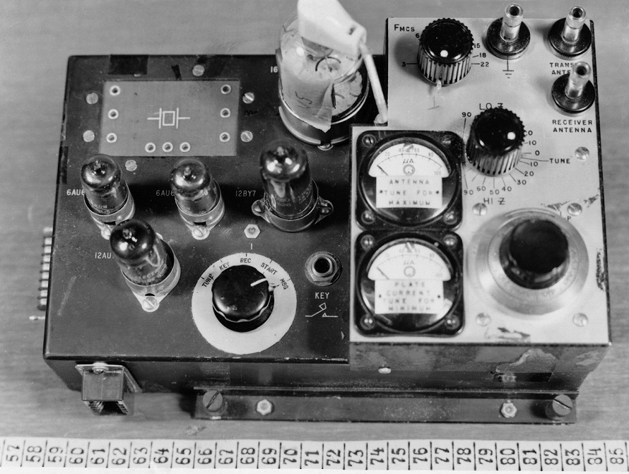
The RS-13 transmitter. This is likely an “A” or “B” version, because the final tube is not a type 1614 (it is possibly a type 1631), and it has additional small tubes that are not mentioned in the RS-13 description.
This view shows a plug-in tuning unit installed in the transmitter. The tuning unit includes a crystal and other components pre-tuned to a specific frequency. This made the transmitter simpler to operate.
RS-13 keyer (tape reader), with a roll of paper tape, plastic marking stencil, IBM “electrographic” pencils and leads, and encryption instructions in German.
Using the stencil and electrographic pencil to mark the tape.