
(c) 1999,2024 Peter McCollum
The RS-49 HF Radio Set
This set, which includes the RR-49 receiver, RT-49 transmitter, and associated RP-49 power supply, is a small agent radio similar in overall function to the RS-6, but smaller and using all solid-state technology. It is an excellent example of agent radio technology from the height of the Cold War.
Development of the receiver started in about 1963. Prototypes were built in CIA labs – the late Bud S. was an engineer on the project. Original production RR-49 receivers were made by Collins Radio Company. A Collins schematic has dates starting at April 1964, with mods up to December 1965. The Collins manual includes copyright dates of 1964, 1965, and 1966; the 2nd edition of the manual is dated 1-Feb-66 (#523-0757606-00251D). A later model of the receiver, the RR-49A, was made by Delco Electronics, as indicated by a Delco manual dated November 1970. The RR-49A is nearly identical to the RR-49 - there are only a few minor circuit changes. The manuals for the RR-49 and RR-49A are mostly a match word-for-word, except for the Calibration chapter.
Development of the RT-49 transmitter was initiated in June of 1962, and two prototypes (plus an RP-49 power supply) were delivered by Feb. 1963. The contractor was TRW, with production facilities in West Virginia (tuning caps inside the RT are marked ‘TRW’, and memos reference the contractor being in Falls Church, VA, and West Virginia). A quantity of 300 transmitters were contracted to be delivered by June 1965, but engineering and production problems caused significant delays – production did not start until September, with the first 27 production units arriving in Feb. 1966, but they were all rejected for poor workmanship. As of June 1966 there were still problems, and much frustration with the contractor.
The RP-49 supply operates from 12 VDC at 5.5 amps. The RP-49 was also made by TRW. There was also work on an RP/A-49 supply, which operates from AC power, but this may have never been completed.
The estimated unit costs in January 1964 were: RT-49, $850; RR-49, $700; RP-49, $550; BS-49, $550.
Note from a user (the late Bud S.):
This set was produced in our lab and was the first to use 'sandwiched' technology by us. We had a very fine clean room where prototypes were produced. Both sensitivity and selectivity are good and it is quite stable. Our clean room was staffed by a bunch of little country ladies... small nimble hands that were used to all kinds of needle work. Good workers, but when they had a "poof" when working on a board they teared up a bit.
The RR-49 receiver can be continuous-tuned, with a tuning dial consisting of a tape that moves under a window; or it can be set to a frequency via a front-panel crystal. It receives AM or CW signals from a random-length wire antenna, and includes a 1 MC crystal calibrator. Power is supplied by either a standard 9V battery in a rear compartment, or from the RS-49's 12V power source when operating as a complete station. Controls include PWR OFF/GAIN, BFO, XTAL IN/OUT, BAND, CAL, TUNE, and FINE TUNE. The TUNE and FINE TUNE controls are mechanically operating the same tuning cap. The circuit uses 10 transistors: RF amp, mixer, IF amp (two), detector, audio, AGC, local osc., calibration osc., and BFO.
The power requirement of the RT-49 transmitter is 42 VDC at 1.4 A. The transmitter has some features that are reminiscent of its predecessors: three tuning controls and three matching indicator lights, a connector to support a GRA-71 type of keyer (KE-8 keyer and CO/B-8C coder), and a low-Z/high-Z antenna matching control. The RT-49 supports keying at up to 1200 WPM. Power is applied through a DB-9 connector (the same type as is now used on PC serial ports). The power supply has the mating connector, and sits directly beside the RT-49 when in operation (there is no cable). The transmitter has a binding post for the receiver's antenna, and there is an internal antenna change-over relay. The transmitter supports a VFO input (unknown type). The circuit includes about 8 transistors, 3 of which are large power types (about the size of a TO-66 case, but without the flange). The final stage appears to be 2 transistors in parallel in a common-base configuration (apparently type PT-1623), each with a 2.5 ohm emitter resistor for current balancing.
RR-49 / RT-49 Specifications |
|
|
|
|
Receiver RR-49 |
Transmitter RT-49 |
Power Supply RP-49 |
Weight |
13 oz. |
about 1.5 lb. |
? |
Dimensions |
3-15/16" X 2-13/16" X 1-9/16" |
5-1/4" X 4" X 1-9/16" |
? (Similar to the RT-49) |
Frequency Bands |
2.970-6.150, 5.925-12.3, 11.850-24.600 MC. |
3-6, 6-12, 12-24 MC. |
|
Power input |
9V internal battery, or 12VDC external; 75 mw, average. |
42 VDC at about 1.4 amps max. |
12 VDC. |
Power Output |
1 mw into 2K ohms. |
About 15 watts avg. |
Provides 42 VDC at about 1.5 amp for the xmtr; 12 VDC for the rcvr; and a floating +/- 12 VDC to operate the KE-8 keyer. |
Other RR-49 specifications, from the Collins manual:
· AM sensitivity: 10 db S+N/N, 0.1 mw, 15 uv input.
· CW sensitivity: 0.1 mw with 5 uv input.
· Battery life: 18-20 hours.
· IF frequency: 455 KC.
· Selectivity: 3db, 5kc; 6db, 12kc; 40db, 16kc.
· Audio bandwidth: 300-2500 cps.
An RR-49 receiver. The dial pointer slides across the window, to adjust for calibration at 1 MC points. There is some backlash in the tuning dial (perhaps due to wear on the dial-tape), but the receiver is stable otherwise.
An RR-49A receiver. This image comes from the Delco manual - note the serial number "000". The "T" shaped protrusion is intended to protect the controls from damage.
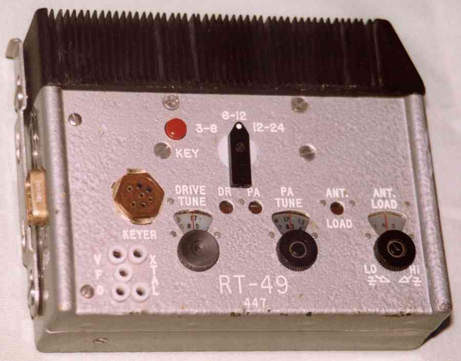
An RT-49 transmitter. The entire top section comprises a heat sink, with 5 devices mounted in it. The DB-9 connector visible on the far left is the DC power input. The antenna/ground/receiver posts are in the upper right, not visible. Note the 3-pin VFO connection - the center pin goes directly to the power connector, and so is probably to provide DC power for the VFO device.
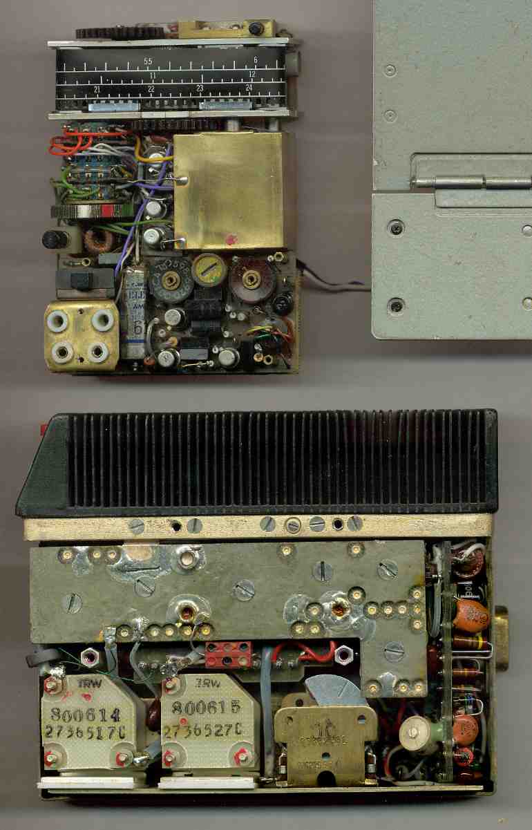
An interior view of the RR-49 and RT-49. Note the metal-tape tuning dial on the receiver; and the unusual tuning caps marked "TRW" in the transmitter (TRW was the contractor for the RT-49 and RP-49). The transmitter's heat sink contains 3 large transistors and 2 smaller devices. Some components have date codes of early to late 1964, so these units were likely assembled in 1965.
An RP-49 power supply. Visible on the right is the DB-9 connector that mates with the transmitter.
Another view of the RP-49 supply. The small 3-pin connector supplies power to the receiver.
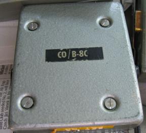
Above are views of the RS-49 coder accessories.
On retirement, some CIA communications officers received a plaque with an RR-49 mounted on it. This occurred until at least 1995, and implies that there was some "old stock" equipment still being stored.
The RR-49 is reported to have been used by Belgian intelligence (the Staatsveiligheid, lit. "state security"). However, apparently the RT-49 was not included in that project - only receivers were delivered.
Click to see the RS-49 set in a case.
Click to see RS-49 tape-coder accessories.
The following table shows the connector pinouts for J-100 (power) and the Keyer connector on the RT-49 transmitter:
Connector pin |
Function |
Wire color |
J-100-1 |
GND |
|
J-100-2 |
+42 VDC input |
Red |
J-100-3 |
N/C |
|
J-100-4 |
+12 V supply to keyer (floating) |
Yellow |
J-100-5 |
-12 V supply to keyer (floating) |
Green |
J-100-6 |
N/C |
|
J-100-7 |
Rcvr antenna |
|
J-100-8 |
N/C |
|
J-100-9 |
VFO power? Goes to center pin on VFO conn. |
White/orange |
|
|
|
Keyer-A |
GND |
Black |
Keyer-B |
T/R relay control (active low) (not used by KE-8) |
White/red |
Keyer-C |
-12 V supply for keyer |
Green |
Keyer-D |
Keyed signal from keyer, active low |
Blue |
Keyer-E |
+42 VDC (not used by KE-8) |
Red |
Keyer-F |
GND (keyed signal) |
|
Keyer-H |
+12 V supply for keyer |
Yellow |


