(c) 1999,2024 Peter McCollum
The RT-4 Transmitter
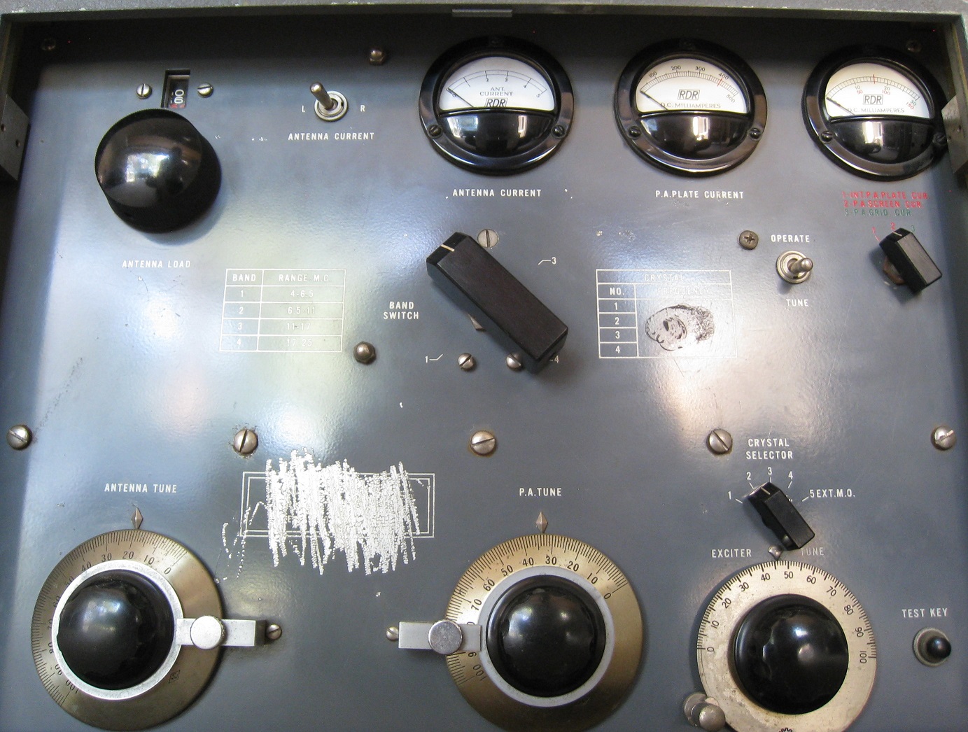
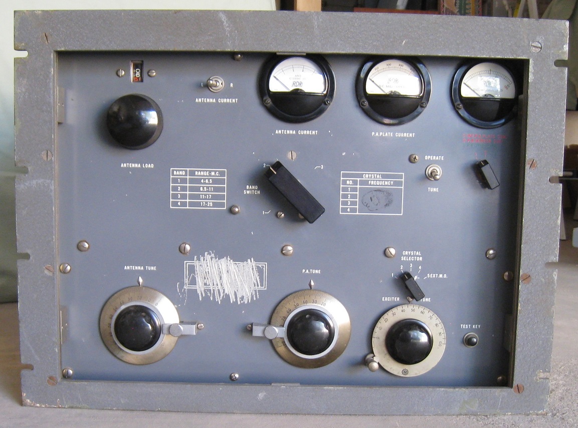
This transmitter is basically a larger version of the RT-1-B, and was also used in embassies. It operates from 4-25 MC in four bands, with four crystal sockets (FT-243 style) plus a selection for an external VFO. The meters include the "RDR" logo. The antenna output is for balanced line, using a final-tank roller inductor with dual taps.
The separate power supply unit provides the final's plate voltage, plus a variac-controlled output of 115V to operate the main transmitter chassis (all other voltages are generated in the transmitter chassis). The supply has two meters: one to indicate the input voltage, and one for the variac-controlled output voltage. The power input can be strapped for either 115 or 230 volt input.
RT-4 Transmitter Specifications |
|
|
|
Transmitter |
Power Supply |
Weight |
about 150 lbs |
about 170 lbs |
Dimensions |
19"W X 14"H X 21"D |
19"W X 14"H X 21"D |
Tube complement |
6AG7 osc./VFO buffer |
866A (two) rect. |
|
2E26 driver |
|
|
4-125A (two) final |
|
|
83 rectifier |
|
|
0C3 regulator |
|
|
0B2 (two) regulators |
|
Frequency Bands |
4-6.5, 6.5-11, 11-17, 17-25 MC |
|
Power Output |
about 500-600 watts |
|
The front panel of the RT-4 transmitter. The identification has been thoroughly scratched off. Author's collection.
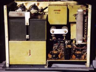
RT-4 rear panel. On the rear panel skirt, the VFO input is visible on the left, and the high voltage connector is on the right. Author's collection.
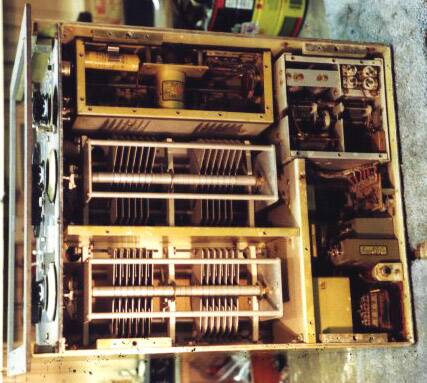
Top view of the RT-4, with the cover removed. Of the two large inductors visible, the top one is adjustable, the other fixed. Note the taps on the coils. Under the two strips near the middle is a pair of bandswitches. The two 4-125A's are visible at the bottom. Crystal sockets are at the lower-right. Author's collection.
Bottom view of the RT-4, with compartment covers removed. Image by Bill Strangfeld.
A 1956 memo discussing modifications to the RT-4
RT-4 notes from a user (the late Bud S.):
I remember installing one in 1952. Once the networks began changing to radio teletype we started using all commercial gear for anything over 100 watts. After we ran out of a lot of the military hand-me-downs such as the Hallicrafters BC-610 (military HT-4) we used a lot of the TMC GPT-750 since it could be used key down at around 500 watts 12 to 14 hours at a time. It was a big old thing with three big pull out drawers. It was complete with its own frequency shift exciter. Only problem was it required a good remotely tunable antenna, otherwise a high standing VSWR was reflected back to ground through the filament transformer. In emergencies I used to put the transformer on styrofoam blocks, lifting it above ground. Of course I locked the bottom drawer to prevent some poor soul from getting electrocuted.
RT-4 and GPT-750 notes from another user, "kwcactus":
[At one time] I was given an RT-4. I put the RT-4 on the air and used it on the ham bands. Finally I tore it apart and rebuilt it as a pair of 4-400A tubes. It was, though, a pretty good transmitter as a stock RT-4, though it was quite heavy for what it did. Incidentally we also used the GPT-750 in some places, and found it to be very reliable. We had it with the FSK deck as well as with the SBE deck. We even had one with the AM modulator, for special purposes. For most installations we used a 48 foot cage dipole, fed with a Harris remote antenna tuner, servo operated. We ran the RTTY version at 500 watts output in 24 hour a day service. The GPT-750 was the mainstay in most embassies around the world. It was also used in remote field sites (such as Quemoy) and in Vietnam. Some (a lot of) embassy stations had two or three GPT-750s, one reserved for RTTY, one for standby/backup, and one for CW operations. The matching receiver, the GPR90RX, never made the grade, and the GPT-750s were teamed with R-390As for the most part.
Following are images of the RT-4's power supply:
Front view. The left meter indicates input AC voltage, the right meter indicates 'output' voltage, which is set to 115 V using the large variac knob. The two switches and round lights are for filament and plate power. Between the meters is a circuit breaker. Author's collection.
Top View.
Bottom view.
Rear view.
Rear view, with case.